Understanding Pulse Width Modulation in Embedded Systems

Pulse Width Modulation (PWM) is a technique that uses a rectangular pulse wave to modulate the pulse width, controlling power delivery to devices effectively. It involves altering the average value of a waveform by switching it on and off within a specified period. PWM has various applications, from power control to data encoding for transmission. Duty cycle, signal average value, and advantages of using PWM are essential concepts in understanding its operation. This article explores PWM types and their significance in embedded systems.

Download Presentation

Please find below an Image/Link to download the presentation.
The content on the website is provided AS IS for your information and personal use only. It may not be sold, licensed, or shared on other websites without obtaining consent from the author. Download presentation by click this link. If you encounter any issues during the download, it is possible that the publisher has removed the file from their server.
E N D
Presentation Transcript
Pulse Width Modulation COE 306: Introduction to Embedded Systems Dr. Aiman El-Maleh Computer Engineering Department College of Computer Sciences and Engineering King Fahd University of Petroleum and Minerals
Next . . . Pulse Width Modulation Definition Pulse Width Modulation Types Generation of PWM PWM Applications LPC176x/5x PWM Computing Platforms COE 306 Introduction to Embedded System KFUPM slide 2
Pulse Width Modulation Definition Pulse-width modulation (PWM) uses a rectangular pulse wave whose pulse width is modulated resulting in the variation of the average value of the waveform. The general purpose of Pulse Width Modulation is to control power delivery, especially to inertial electrical devices. The on-off behavior changes the average power of signal. Output signal alternates between on and off within a specified period. A secondary use of PWM is to encode information for transmission. Computing Platforms COE 306 Introduction to Embedded System KFUPM slide 3
Duty Cycle The Duty Cycle is a measure of the time the modulated signal is in its high state. It is generally recorded as the percentage of the signal period where the signal is considered on. On Time On Off = 100 % Duty Cycle Period VH Duty Cycle (D) VL Period (T) Computing Platforms COE 306 Introduction to Embedded System KFUPM slide 4
Signal Average Value Average value of a pulse waveform f(t) with period T, low value VL, high value VH can be found as: On Off 1 T T = ( ) y f t dt VH 0 Duty Cycle (D) ( ) = + 1 V D V D V VL avg H L Period (T) In general VL is 0; Vavg = D . VH The average value of the signal is directly dependent on the duty cycle D. Computing Platforms COE 306 Introduction to Embedded System KFUPM slide 5
Advantages of Using PWM Average value proportional to duty cycle Low power used in transistors used to switch the signal, and fast switching possible due to MOSFETS and power transistors at speeds in excess of 100 kHz To fulfill partial power requirements, variable resistance devices such as rheostats were used to control the current entering a device (e.g. sewing machines) Alleviates the problem of high heat loses through resistive elements at intermediate voltage points Computing Platforms COE 306 Introduction to Embedded System KFUPM slide 6
Pulse Width Modulation Types There are three commonly used types of PWM defined by which edge of the analog signal is to be modulated Lead Edge Modulation: The lead edge of the trigger signal is fixed to the leading edge of the time spectrum and the leading (rising) edge is modulated. Trail Edge Modulation: The trail edge of the trigger signal is fixed to the trailing edge of the time spectrum and the trailing (falling) edge is modulated. Pulse Center Two Edge Modulation: The pulse center is fixed in the middle of the time spectrum and both edges are modulated about the center of the trigger signal. Computing Platforms COE 306 Introduction to Embedded System KFUPM slide 7
Pulse Width Modulation Types Computing Platforms COE 306 Introduction to Embedded System KFUPM slide 8
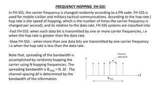
Analog Generation of PWM The Intersective Method: Allows for analog creation of PWM signal through noting intersections between a sawtooth trigger signal and a reference sinusoid. Length of pulses is dependent upon intersection of reference sinusoid and trigger signal. When sinusoid is greater than trigger signal, PWM pulse is switched to on/high position, otherwise it is switched to off/low. Computing Platforms COE 306 Introduction to Embedded System KFUPM slide 9
Analog Generation of PWM Analog Signal Trigger Signal PWM Signal Computing Platforms COE 306 Introduction to Embedded System KFUPM slide 10
Delta Modulation Using reference analog signal, set of limits set by constant offset, and the integrated PWM signal. Output is integrated, will increase/decrease toward limits set around reference by constant offset. Whenever output comes into contact with one of limits around reference, PWM signal will switch modes. Computing Platforms COE 306 Introduction to Embedded System KFUPM slide 11
Delta-Sigma Modulation An error signal is developed by subtracting the PWM signal from a reference sinusoid and then integrated. When this integrated error signal reaches a set of defined limits, the PWM signal will switch modes. +v 0 -v +v 0 -v Computing Platforms COE 306 Introduction to Embedded System KFUPM slide 12
Time Proportioning PWM Generation Microcontrollers use a counter that increments periodically and is reset at the end of every period of the PWM. When the counter value is more than the reference value, the PWM output changes state from high to low (or low to high). The incremented and periodically reset counter is the discrete version of the intersecting method's sawtooth. The analog comparator of the intersecting method becomes a simple integer comparison between the current counter value and the digital reference value. Computing Platforms COE 306 Introduction to Embedded System KFUPM slide 13
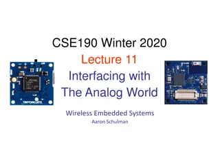
PWM Applications PWM has many useful applications in embedded systems. The main two categories are: When a microcontroller does not have a DAC circuit, PWM can be used to modulate different analog values. Some devices are built to be used with PWM. The most famous example is servo motors. Controlling the brightness of LED by adjusting the duty cycle With an RGB (red green blue) LED, you can control how much of each of the three colors you want in the mix of color by dimming them with various amounts. Computing Platforms COE 306 Introduction to Embedded System KFUPM slide 14
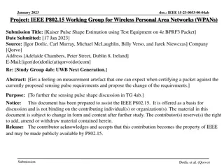
PWM Applications Pulse width modulation can be used to control the angle of a servo motor attached to something mechanical like a robot arm. Servos have a shaft that turns to specific position based on its control line. Frequency/period are specific to controlling a specific servo. Robotic claw controlled by a servo motor using pulse-width modulation Computing Platforms COE 306 Introduction to Embedded System KFUPM slide 15
PWM Applications A typical servo motor expects to be updated every 20 ms with a pulse between 1 ms and 2 ms, or in other words, between a 5 and 10% duty cycle on a 50 Hz waveform. With a 1.5 ms pulse, the servo motor will be at the natural 90 degree position, With a 1 ms pulse, the servo will be at the 0 degree position, With a 2 ms pulse, the servo will be at 180 degrees. Computing Platforms COE 306 Introduction to Embedded System KFUPM slide 16
PWM Applications PWM can be used to transmit data in telecommunication Clock signal is found inside PWM signal More resistant to noise effects than binary data alone Effective at data transmission over long distance transmission lines Computing Platforms COE 306 Introduction to Embedded System KFUPM slide 17
PWM Applications DC voltage can be regulated by PWM to modify output voltage 12v supply controlled by PWM at 50% duty cycle can create an output signal of 6v Use smoothing filters to get DC output Efficiency of a PWM voltage regulator: ~90% Efficiency of linear regulator: ~50% Linear regulators suffer from power dissipation proportional to the output current High current also implies Ohmic Heating of elements Z + = 2 V V out in Z Z 1 2 Computing Platforms COE 306 Introduction to Embedded System KFUPM slide 18
PWM Applications Computing Platforms COE 306 Introduction to Embedded System KFUPM slide 19
LPC176x/5x PWM Seven match registers allow up to 6 single edge controlled or 3 double edge controlled PWM outputs, or a mix of both types. Single-edge controlled PWM outputs all go high at beginning of each cycle unless output is a constant low. Double edge controlled PWM outputs can have either edge occur at any position within a cycle. This allows for both positive going and negative going pulses. Pulse period and width can be any number of timer counts. This allows complete flexibility in the trade-off between resolution and repetition rate. All PWM outputs will occur at the same repetition rate. Computing Platforms COE 306 Introduction to Embedded System KFUPM slide 20
PWM block diagram Computing Platforms COE 306 Introduction to Embedded System KFUPM slide 21
Sample Waveform for Single and Double Edge Control Computing Platforms COE 306 Introduction to Embedded System KFUPM slide 22
LPC176x/5x PWM Registers TCR (Timer Control Register): TCR is used to control the Timer Counter functions. The Timer Counter can be disabled or reset through the TCR. Bit 0: for enabling the counter Bit 1: for resetting timer counter and prescale counter Bit 3: to enable PWM LPC_PWM1->TCR |= 1 | (1 << 3); // Enable Counter & PWM TC (Timer Counter): The 32-bit TC is incremented every PR+1 cycles of PCLK. The TC is controlled through the TCR. PR (Prescale Register): The TC is incremented every PR+1 cycles of PCLK. Computing Platforms COE 306 Introduction to Embedded System KFUPM slide 23
LPC176x/5x PWM Registers PC (Prescale Counter): The 32-bit PC is a counter which is incremented to the value stored in PR. When the value in PR is reached, the TC is incremented. PCR (PWM Control Register): Enables PWM outputs and selects PWM channel types as either single edge or double edge controlled. Bits 2-6 generate PWMSEL2 to PWMSEL6 Bits 9-14 generate PWMENA1 to PWMENA6 IR (Interrupt Register): The IR can be written to clear interrupts. The IR can be read to identify which of eight possible interrupt sources are pending. Computing Platforms COE 306 Introduction to Embedded System KFUPM slide 24
LPC176x/5x PWM Registers MCR (Match Control Register): The MCR is used to control if an interrupt is generated and if the TC is reset when a Match occurs. 3 bits for each match register Bits 0-2 for MR0, Bits 3-5 for MR1, etc. 1st bit generates an interrupt on match, 2nd bit resets TC on match, 3rd bit stops TC and PC by resetting PCR[0] MR0 (Match Register 0): MR0 can be enabled in MCR to reset TC, stop both TC and PC, and/or generate an interrupt when it matches the TC. In addition, a match between this value and TC sets any PWM output that is in single-edge mode. Computing Platforms COE 306 Introduction to Embedded System KFUPM slide 25
LPC176x/5x PWM Registers MRi (Match Register i): MRi can be enabled in MCR to reset TC, stop both TC and PC, and/or generate an interrupt when it matches the TC. In addition, a match between this value and TC clears PWMi in either edge mode, and sets PWMi+1 if it s in double-edge mode. LER (Load Enable Register): Enables use of new PWM match values. Bits 0 to 6 correspond to Match 0 to Match 6 registers Writing a one to any of those bits allows the last value written to the corresponding PWM Match register to become effective when the timer is next reset by a PWM Match event. Computing Platforms COE 306 Introduction to Embedded System KFUPM slide 26