Understanding Interrupt Handling in MSP430 Embedded Systems
This lab explores the intricacies of handling interrupts in MSP430, covering types of interrupts, enabling interrupts, and the execution flow when an interrupt is requested and serviced. Topics include interrupt service routines, clearing interrupt flags, and enabling/disabling maskable interrupts. Gain insights into managing interrupts efficiently for embedded systems design.

Download Presentation

Please find below an Image/Link to download the presentation.
The content on the website is provided AS IS for your information and personal use only. It may not be sold, licensed, or shared on other websites without obtaining consent from the author. Download presentation by click this link. If you encounter any issues during the download, it is possible that the publisher has removed the file from their server.
E N D
Presentation Transcript
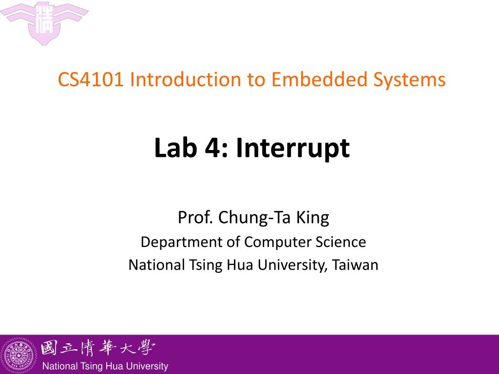
CS4101 Introduction to Embedded Systems Lab 4: Interrupt Prof. Chung-Ta King Department of Computer Science National Tsing Hua University, Taiwan National Tsing Hua University
Introduction In this lab, we will learn interrupts of MSP430 Handling interrupts in MSP430 Handling interrupts of Timer_A in MSP430 Handling interrupts of port P1 in MSP430 Writing an interrupt service routine 1 National Tsing Hua University
Three Types of Interrupts in MSP430 System reset: Power-up, external reset, Watchdog Timer, flash key violation, PC out-of-range, etc. Always take (Non)-maskable interrupt (NMI): RST/NMI pin, oscillator fault, flash access violation Cannot be masked; but still need bits to be set in special peripheral registers Maskable interrupt Enable the interrupt Prepare the interrupt service routine (ISR) and link it to the interrupt 2 National Tsing Hua University
Enable an Interrupt On MSP430, an interrupt will be detected and serviced if The global interrupt-enable (GIE) bit in Status Register (SR) in CPU is set A peripheral device enables interrupt For Timer_A: TAIE bit in TACTL register, CCIE bit in TACCTLx register The peripheral signals an interrupt For Timer_A: TAIFG, CCIFG 3 National Tsing Hua University
Ex: Timer_A Interrupt Enabling TACTL TACCTL 4 National Tsing Hua University
When an Interrupt Is Requested Any currently executing instruction is completed. MCLK is started if the CPU was off. The PC, which points to the next instruction, is pushed onto the stack. The SR is pushed onto the stack. The interrupt with the highest priority is selected. The interrupt request flag is cleared automatically for interrupts that have a single source. The SR is cleared, and other maskable interrupts are disabled. The starting address of ISR is loaded into the PC and the CPU starts to execute the ISR at that address. These operations take about 6 cycles 5 National Tsing Hua University
After an Interrupt Is Serviced An interrupt service routine must always finish with the return from interrupt instruction reti: The SR pops from the stack. All previous settings of GIE and the mode control bits are now in effect. enable other maskable interrupts and restores the previous low-power mode if there was one. The PC pops from the stack and execution resumes at the point where it was interrupted. Alternatively, the CPU stops and the device reverts to its low-power mode before the interrupt. The original program runs as if there were no interrupt. 6 National Tsing Hua University
Where to Find ISRs? MSP430 uses vectored interrupts Each ISR has its own vector (starting address), which is stored at a predefined address in a vector table at the end of the program memory (addresses 0xFFE0 ~ 0xFFFF). The vector table is at a fixed location, but the ISRs themselves can be located anywhere in memory. 7 National Tsing Hua University
System Interrupt Word Address Interrupt Source Interrupt Flag Priority Power-up/external reset/Watchdog Timer+/flash key viol./PC out-of-range NMI/Oscillator Fault/ Flash access viol. Timer1_A3 Timer1_A3 Comparator_A+ Watchdog Timer+ Timer0_A3 PORIFG RSTIFG WDTIFG KEYV NMIIFG/OFIFG/ ACCVIFG TA1CCR0 CCFIG TA1CCR1/2 CCFIG, TAIFG CAIFG WDTIFG TA0CCR0 CCIFG 31 Reset 0FFFEh (highest) Non-maskable 0FFFCh 30 maskable maskable maskable maskable maskable 0FFFAh 0FFF8h 0FFF6h 0FFF4h 0FFF2h 29 28 27 26 25 Timer0_A3 TA0CCR1/2 CCIFG, TAIFG maskable 0FFF0h 24 0FFEEh 0FFECh 0FFEAh 23 22 21 ADC10 ADC10IFG maskable 0FFE8h 20 I/O Port P2 (8) P2IFG.0 to P2IFG.7 maskable 0FFE6h 19 I/O Port P1 (8) P1IFG.0 to P1IFG.7 maskable 0FFE4h 18 0FFE2h 0FFE0h 0FFDEh 0FFCDh 17 16 8 Unused 15 - 0 National Tsing Hua University
Outline Handling interrupts in MSP430 Handling interrupts of Timer_A in MSP430 Handling interrupts of port P1 in MSP430 Writing an interrupt service routine 9 National Tsing Hua University
Interrupts from Timer_A Interrupts can be generated by the timer itself (flag TAIFG) and each capture/compare block (flag TACCRx CCIFG) TAIFG CCIFG TACTL TACCTL 10 National Tsing Hua University
Two Interrupt Vectors for Timer_A For TACCR0 CCIFG (high priority): CCIFG0 flag is cleared automatically when serviced For all other CCIFG flags and TAIFG In compare mode, any CCIFG flag is set if TAR counts to the associated TACCRx value Flags are not cleared automatically, because need to determine who made the interrupt request Can use software (ISR) to poll the flags slow Use hardware: Timer_A interrupt vector register (TAIV) 11 National Tsing Hua University
TAIV On an interrupt, TAIV contains a number indicating highest priority enabled interrupt Any access of TAIV resets the highest pending interrupt flag. If another interrupt flag is set, another interrupt is immediately generated 12 National Tsing Hua University
Sample Code for Timer_A Interrupt Toggle LEDs using interrupts from Timer_A in up mode #include <io430x11x1.h> // Specific device #include <intrinsics.h> // Intrinsic functions #define LED1 BIT0 void main(void) { WDTCTL = WDTPW|WDTHOLD; // Stop watchdog timer P1OUT = LED1; P1DIR = LED1; TA0CCR0 = 49999; // Upper limit of count for TAR TA0CCTL0 = CCIE; // Enable interrupts TA0CTL = MC_1|ID_3|TASSEL_2|TACLR; // Up mode, divide clock by 8, clock from SMCLK, clear __enable_interrupt(); // Enable interrupts (intrinsic) for (;;) { } // Loop forever doing nothing } // Interrupt service routine for Timer0_A #pragma vector = TIMER0_A0_VECTOR __interrupt void TA0_ISR (void){ P1OUT = LED1; // Toggle LED } 13 National Tsing Hua University
Sample Code Explained #pragma line associates the function with a particular interrupt vector __interrupt keyword names the function Compiler will generate code to store address of the function in the vector and to use reti rather than ret at the end of the function An intrinsic function, __enable_interrupt() sets the GIE bit and turn on interrupts It is declared in intrinsics.h 14 National Tsing Hua University
Outline Handling interrupts in MSP430 Handling interrupts of Timer_A in MSP430 Handling interrupts of port P1 in MSP430 Writing an interrupt service routine 15 National Tsing Hua University
Interrupts on Port 1 Ports P1 and P2 can request an interrupt when the value on an input pin changes Registers of P1 for interrupt: Port P1 interrupt enable, P1IE: enables interrupts when the value on an input pin changes, by setting appropriate bits of P1IE to 1; off (0) by default Port P1 interrupt edge select, P1IES: can generate interrupts either on a positive edge (0), when the input goes from low to high, or on a negative edge (1) Port P1 interrupt flag, P1IFG: a bit is set when the selected transition has been detected on the input, and an interrupt is requested if it has been enabled. 16 National Tsing Hua University
Interrupts on Port 1 A single interrupt vector for the whole port An interrupt will be requested whenever one or more interrupt-enabled pins on the port detect the signal transitions The ISR must check P1IFG to determine the bit that caused the interrupt This bit must be cleared explicitly 17 National Tsing Hua University
Sample Code for P1 A hi/low transition on P1.4 triggers P1_ISR to toggles P1.0 void main(void) { WDTCTL = WDTPW + WDTHOLD; // Stop watchdog timer P1DIR = 0x01; // P1.0 output, else input P1OUT = 0x10; // P1.4 set, else reset P1REN |= 0x10; // P1.4 pullup P1IE |= 0x10; // P1.4 interrupt enabled P1IES |= 0x10; // P1.4 Hi/lo edge P1IFG &= ~0x10; // P1.4 IFG cleared _BIS_SR(GIE); // Enter interrupt while(1); // Loop forever } #pragma vector=PORT1_VECTOR __interrupt void Port_1(void) { P1OUT ^= 0x01; // P1.0 = toggle P1IFG &= ~0x10; // P1.4 IFG cleared } 18 National Tsing Hua University
Lab 4 Basic 1: Flash red and green LED at 1 Hz 1 based on the interrupt from TA0R of Timer0_A driven by ACLK sourced by VLO. The red LED should be on for 0.4 sec and off for 0.6 sec based on the interrupt from TA0CCR0. The green LED should be on for 0.2 sec and off for 0.8 sec, based on the interrupt from TA0CCR1. Hint: For different devices, the names of the Interrupt Vectors may be different. Please check the header file for the correct name. 19 National Tsing Hua University
Lab 4 Hint The name of the interrupt vector for TA0CCR1, TA0CCR2, and TA0R is TIMER0_A1_VECTOR. All three interrupts will cause the CPU to run the same ISR at TIMER0_A1_VECTOR. To detect whether it is TA0CCR1, TA0CCR2, or TA0R that causes the interrupt, please check the register TA0IV. Note that TA0IV will be reset automatically when you read it. Thus, you need to read TA0IV into a local variable first before you check its bits. 20 National Tsing Hua University
Lab 4 Basic 2: Write an ISR for the button that would switch the behavior of the two LEDs in Basic 1. The ISR is requested whenever the button is released. Hint: PORT1_VECTOR as interrupt type, P1IFG as interrupt flag List the assembly code and point out the location of ISR. 21 National Tsing Hua University
Lab 4 Bonus: measure the duration of button down Write the button ISR so that it detects button down as well as up in an alternative fashion. Hint: You may need to use a variable to track the state of the button. When button is down, start a timer with Timer0_A. When the button is released, stop the timer and report the amount of time (in seconds) that the button is pressed on the expression window of CCS. Timer0_A may overflows several times during this period. You need to use interrupts to track the number of times that the timer overflows. 22 National Tsing Hua University