Temperature Control Strategies in Industrial Reactor Design


1
R
e
f
:
S
e
i
d
e
r
e
t
a
l
,
P
r
o
d
u
c
t
a
n
d
p
r
o
c
e
s
s
d
e
s
i
g
n
p
r
i
n
c
i
p
l
e
s
,
3
r
d
e
d
.
,
W
i
l
e
y
,
2
0
1
0
.

Temperature Control
Temperature control is an important consideration in reactor
design.
Adiabatic operation is always considered first because it
provides the simplest and least-expensive reactor.
However, when reactions are highly exothermic or endothermic,
some methods must be used for controlling the temperature of
reactor such as:
2
• Heat-exchanger reactor (a)
• Use of diluent (b)
• A series of beds with inter- heater or cooler (c)
• Cold-shot cooling or hot-shot heating (d)
3
Industrial Examples
A useful measure of the degree of exothermicity or
endothermicity is the
Adiabatic Temperature Rise (ATR)
for
complete reaction with reactants in the stoichiometric ratio.
An industrial example of heat-exchanger reactor :
Phthalic
anhydide produced by the oxidation of ortho-xylene with air in
the presence of vanadium pentoxide catalyst particles. The
reaction, which is carried out at about 375
o
C and 1.2 atm, is
highly exothermic with an ATR of about 1170
o
C, even with
nitrogen in the air providing some dilution. Hundreds of long
tubes of small diameter, inside the shell, are packed with catalyst
particles and through which the reacting gas passes downward.
4
Industrial Examples
A heat-transfer medium consisting of a sodium nitrite-potassi-
um nitrate-fused salts circulates outside the tubes through the
shell. The heat transfer rate distribution is not adequate to
maintain isothermal condition, but its temperature changes is
less than 40
o
C.
An industrial example of diluent usage :
Styrene is produced
by the catalytic dehydrogenation of ethylbenzene at 1.2 atm and
575
o
C. The reaction is sufficiently endothermic, with an ATR of
about -460
o
C. To maintain a reasonable temperature, a large
amount of steam (inert) that preheated to 625
o
C, is added to the
feed (molar ratio of steam to ethylbenzene is about 20:1).
5
Industrial Examples
An industrial example of inter-cooler usage :
Sulfur trioxide,
which is used to make sulfuric acid, is produced by catalytic
oxidation of sulfur dioxide in air with vanadium pentoxide
catalyst particles at 1.2 atm and 450
o
C. Adiabatic operation is
not feasible because of an ATR of about 710
o
C, even with
nitrogen in the air providing some dilution. Hence, the reactor
system consists of four adiabatic reactor beds, of the same
diameter but different height, in series, with a heat exchanger
between each pair of beds.
When the ATR is higher, such as in the manufacture of ammonia
from synthesis gas,
the cold-shot design
is recommended.
6
Desired Temperature Trajectory
For 1-D fixed-bed catalytic reactors, it is desirable to reduce the
vessel volume to a minimum. This objective can be achieved by
matching the trajectory of the mass- and energy-balance
equations along the length of reactor (
X
(
z
),
T
(
z
)), to the
trajectory corresponding to the maximum reaction rate, (
X
*,
T
*),
as closely as possible.
Thus, tube-cooled (or heated) reactors, cold-shot (or hot-shot)
converters, and multiple adiabatic beds with inter-coolers (or
inter-heaters) need to be carefully designed in such a way that
(
X
(
z
),
T
(
z
)) ≈ (
X
*,
T
*).
7
Desired Temperature Trajectory
8
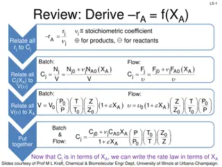
As an example , consider an
exothermic reversible reaction in a
PFR. For this case, the rate of the
reverse reaction increases more
rapidly with increasing temperature
than the rate of forward reaction.
Also, the reverse reaction is slow and
the forward reaction is fast at low
temperature. Thus, for a maximum
rate of reaction, the temperature
should be high at low conversions
and low at high conversions.
Desired Temperature Trajectory
9
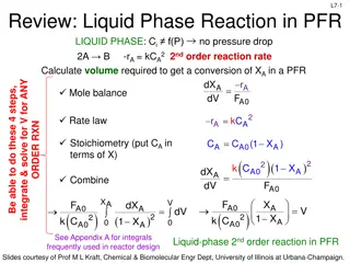
The feed enters at point A (
T
A
,
X
1
).
If the entering temperature cannot be
increased, it is best to operate isoth-
ermally at
T
A
until the conversion at
point C is reached, and than follow
the optimal profile CB to the desired
conversion (
X
4
).
Alternatively, a larger reactor volume
will be needed, if isothermal
operation is used (trajectory ACD).
If instead of a PFR, a CSTR were used, the optimal operating
temperature for achieving
X
4
would be
T
B
,
which corresponds to
the maximum reaction rate for that conversion.
Multiple Steady States in an Auto-
thermal Reactor
10
The reactor feed temperature has
an important effect on the
stability of an auto-thermal
reactor, that is, a reactor whose
feed is preheated by its effluent.
For a reversible exothermic reaction, as in ammonia synthesis,
the heat generation rate varies nonlinearly with reaction
temperature, with a maximum at some intermediate temperature.
In contrast, the rate of heat removal is almost linear with the
reaction temperature, with a slope dependent on the degree of
heat exchange between the outlet and the inlet.
Multiple Steady States in an Auto-
thermal Reactor
11
The intersection of line (b) and
curve (a) sometimes leads to
three possible operating
conditions: (O) the non-reacting
state (stable), (I) the ignition
point (unstable), and (S) the
desired operating point (stable).
The temperature difference between operating points I and S is
called
stability margin
. Clearly, operation at S with larger
stability margin would be more robust to disturbances.
Thus a
design with increased rate of heat transfer (line b
’
) and a design
without considering the decreasing of catalyst activity (line a
’
),
can lead to loss of stability.
Example 7.3:
Optimal Bypass Distribution in a Three-
Bed, Cold-Shot Ammonia Synthesis Converter
A reactor for synthesis of ammonia consists of three cylindrical,
2-m-diameter adiabatic beds, packed with catalyst for bed
lengths of 1.5 m, 2 m, and 2.5 m, respectively. The reactor feed
is split into three branches, with the 1
st
branch becoming the
main feed entering the 1
st
bed after being preheated by the hot
reactor effluent from the 3
rd
bed. The 2
nd
and 3
rd
branches, with
flow fractions of
φ
1
and
φ
2
, provide cold-shot cooling at the 1
st
and 2
nd
bed effluents.
12
Example 7.3:
Optimal Bypass Distribution in a Three-
Bed, Cold-Shot Ammonia Synthesis Converter
As summarized in the following Table, the reactor feed consists
of two sources, the first of which is a make-up feed stream
mainly hydrogen and nitrogen (synthesis gas) in stoichiometric
molar ratio of 3:1. The second feed is a recycle stream consisting
of unreacted synthesis gas, recovered after removing the
ammonia product.
It is desired to optimize the allocation of
the bypass fractions to maximize the ammonia production.
13
Example 7.3: Solution
Ammonia is synthesized by the following reversible reaction:
After multiplying the rate equation by 2 and changing the unit of
partial pressure to Pascal, we have:
14
Example 7.3: Solution
At first, a value of 0.1 is assumed for each bypass fraction and
the process was simulated in ASPEN PLUS (the PR EOS was
used for property prediction). The simulated process was saved
with filename: <example7_3_current.bkp>.
For founding the optimum temperature trajectory based on the
NH
3
mole percent and the rate of reaction, the partial pressure of
H
2
and N
2
must be expressed in terms of NH
3
mole fraction.
This can be done by component mass balance as follows:
Where the
F
0
is the total molar flow rate of the combined feed
and
ξ
is the molar extent of reaction.
15
Example 7.3: Solution
Where
x
f,i
is the feed mole fraction of species
i
.
Consequently, the rate of reaction can be computed as a function
of the temperature and mole percent of NH
3
, as shown in the
following figure for operating pressure of 150 atm.
16
The above figure can be reproduced in MATLAB by running the
m-file: <example7_3_current.m>. As can be seen from the
results by using a value of 0.1 for each bypass fraction, the conc.
of ammonia in the effluent stream is 12.9%.
17
Example 7.3: Solution
To maximize the ammonia production in the reactor, the
following optimization problem must be solved:
The first constraint refers to the reactor model. The second and
third constraints are selected for achieving a suitable stability
margin. The last constraint is arbitrary.
18
Example 7.3: Solution
The above optimization problem was solved by Successive
Quadratic Programming (SQP) method in ASPEN PLUS (the
filename is: <example7_3_optim.bkp>). The final ammonia
composition in the reactor effluent is 16.1 mol%, obtained
with optimal bypass fractions
φ
1
=0.23 and
φ
2
=0.24.
The composition-temperature trajectories for the optimal
bypass distribution, is shown in the following figure. This
figure can be reproduced in MATLAB by running the m-
file:<example7_3_optim.m>.
19
Example 7.3: Solution
20
Investigate the performance of the optimized process, if the
catalyst activity decreases by a factor of 0.2 (80% decrease
in catalyst activity).
Temperature control plays a critical role in reactor design, especially when dealing with highly exothermic or endothermic reactions. Adiabatic operation is typically the preferred choice, but various methods such as heat-exchanger reactors, diluent usage, and inter-cooler systems are employed based on the nature of the reaction. Industrial examples like the production of phthalic anhydride and styrene showcase the application of these temperature control strategies to ensure safe and efficient operation in chemical processes.

Download Presentation

Please find below an Image/Link to download the presentation.
The content on the website is provided AS IS for your information and personal use only. It may not be sold, licensed, or shared on other websites without obtaining consent from the author. Download presentation by click this link. If you encounter any issues during the download, it is possible that the publisher has removed the file from their server.
E N D
Presentation Transcript
Ref: Seider et al, Product and process design principles, 3rd ed., Wiley, 2010. 1
Temperature Control Temperature control is an important consideration in reactor design. Adiabatic operation is always considered first because it provides the simplest and least-expensive reactor. However, when reactions are highly exothermic or endothermic, some methods must be used for controlling the temperature of reactor such as: 2
Heat-exchanger reactor (a) Use of diluent (b) A series of beds with inter- heater or cooler (c) Cold-shot cooling or hot-shot heating (d) 3
Industrial Examples A useful measure of the degree of exothermicity or endothermicity is the Adiabatic Temperature Rise (ATR) for complete reaction with reactants in the stoichiometric ratio. An industrial example of heat-exchanger reactor : Phthalic anhydide produced by the oxidation of ortho-xylene with air in the presence of vanadium pentoxide catalyst particles. The reaction, which is carried out at about 375 oC and 1.2 atm, is highly exothermic with an ATR of about 1170 oC, even with nitrogen in the air providing some dilution. Hundreds of long tubes of small diameter, inside the shell, are packed with catalyst particles and through which the reacting gas passes downward. 4
Industrial Examples A heat-transfer medium consisting of a sodium nitrite-potassi- um nitrate-fused salts circulates outside the tubes through the shell. The heat transfer rate distribution is not adequate to maintain isothermal condition, but its temperature changes is less than 40 oC. An industrial example of diluent usage : Styrene is produced by the catalytic dehydrogenation of ethylbenzene at 1.2 atm and 575 oC. The reaction is sufficiently endothermic, with an ATR of about -460 oC. To maintain a reasonable temperature, a large amount of steam (inert) that preheated to 625 oC, is added to the feed (molar ratio of steam to ethylbenzene is about 20:1). 5
Industrial Examples An industrial example of inter-cooler usage : Sulfur trioxide, which is used to make sulfuric acid, is produced by catalytic oxidation of sulfur dioxide in air with vanadium pentoxide catalyst particles at 1.2 atm and 450 oC. Adiabatic operation is not feasible because of an ATR of about 710 oC, even with nitrogen in the air providing some dilution. Hence, the reactor system consists of four adiabatic reactor beds, of the same diameter but different height, in series, with a heat exchanger between each pair of beds. When the ATR is higher, such as in the manufacture of ammonia from synthesis gas, the cold-shot design is recommended. 6
Desired Temperature Trajectory For 1-D fixed-bed catalytic reactors, it is desirable to reduce the vessel volume to a minimum. This objective can be achieved by matching the trajectory of the mass- and energy-balance equations along the length of reactor (X(z), T(z)), to the trajectory corresponding to the maximum reaction rate, (X*, T*), as closely as possible. Thus, tube-cooled (or heated) reactors, cold-shot (or hot-shot) converters, and multiple adiabatic beds with inter-coolers (or inter-heaters) need to be carefully designed in such a way that (X(z), T(z)) (X*, T*). 7
Desired Temperature Trajectory As an example , consider an exothermic reversible reaction in a PFR. For this case, the rate of the reverse reaction increases more rapidly with increasing temperature than the rate of forward reaction. Also, the reverse reaction is slow and the forward reaction is fast at low temperature. Thus, for a maximum rate of reaction, the temperature should be high at low conversions and low at high conversions. 8
Desired Temperature Trajectory The feed enters at point A (TA , X1). If the entering temperature cannot be increased, it is best to operate isoth- ermally at TA until the conversion at point C is reached, and than follow the optimal profile CB to the desired conversion (X4). Alternatively, a larger reactor volume will be needed, if isothermal operation is used (trajectory ACD). If instead of a PFR, a CSTR were used, the optimal operating temperature for achieving X4 would be TB, which corresponds to the maximum reaction rate for that conversion. 9
Multiple Steady States in an Auto- thermal Reactor The reactor feed temperature has an important effect on the stability of an auto-thermal reactor, that is, a reactor whose feed is preheated by its effluent. For a reversible exothermic reaction, as in ammonia synthesis, the heat generation rate varies nonlinearly with reaction temperature, with a maximum at some intermediate temperature. In contrast, the rate of heat removal is almost linear with the reaction temperature, with a slope dependent on the degree of heat exchange between the outlet and the inlet. 10
Multiple Steady States in an Auto- thermal Reactor The intersection of line (b) and curve (a) sometimes leads to three possible operating conditions: (O) the non-reacting state (stable), (I) the ignition point (unstable), and (S) the desired operating point (stable). The temperature difference between operating points I and S is called stability margin. Clearly, operation at S with larger stability margin would be more robust to disturbances.Thus a design with increased rate of heat transfer (line b ) and a design without considering the decreasing of catalyst activity (line a ), can lead to loss of stability. 11
Example 7.3: Optimal Bypass Distribution in a Three- Bed, Cold-Shot Ammonia Synthesis Converter A reactor for synthesis of ammonia consists of three cylindrical, 2-m-diameter adiabatic beds, packed with catalyst for bed lengths of 1.5 m, 2 m, and 2.5 m, respectively. The reactor feed is split into three branches, with the 1st branch becoming the main feed entering the 1st bed after being preheated by the hot reactor effluent from the 3rd bed. The 2nd and 3rd branches, with flow fractions of 1 and 2, provide cold-shot cooling at the 1st and 2nd bed effluents. 12
Example 7.3: Optimal Bypass Distribution in a Three- Bed, Cold-Shot Ammonia Synthesis Converter As summarized in the following Table, the reactor feed consists of two sources, the first of which is a make-up feed stream mainly hydrogen and nitrogen (synthesis gas) in stoichiometric molar ratio of 3:1. The second feed is a recycle stream consisting of unreacted synthesis gas, recovered after removing the ammonia product. It is desired to optimize the allocation of the bypass fractions to maximize the ammonia production. 13
Example 7.3: Solution Ammonia is synthesized by the following reversible reaction: + 5 . 0 N 5 . 1 H NH 2 2 3 91000 RT 140000 RT = 3 . 1 4 5 . 0 N 5 . 1 H 10 10 exp 10 exp R P P P NH a 2 2 3 kmol of N consumed 3 kJ = = = = , K , . 8 314 , atm 2 R T R P a i m s kmol K After multiplying the rate equation by 2 and changing the unit of partial pressure to Pascal, we have: 91000 RT 140000 RT . 1 = 6 5 . 0 N 5 . 1 H 5 95 10 exp . 2 57 10 exp r P P P k NH 2 2 3 kmol 3 kJ = = = = : , K , . 8 314 , Pa where r T R iP k m s kmol K 14
Example 7.3: Solution At first, a value of 0.1 is assumed for each bypass fraction and the process was simulated in ASPEN PLUS (the PR EOS was used for property prediction). The simulated process was saved with filename: <example7_3_current.bkp>. For founding the optimum temperature trajectory based on the NH3 mole percent and the rate of reaction, the partial pressure of H2 and N2 must be expressed in terms of NH3 mole fraction. This can be done by component mass balance as follows: = = in , Ar out , Ar in , CH out , CH , 4 4 n n n n = = = = + 5 . 0 , 5 . 1 , n n n n n n N , out N , in H , out H in n , NH , out NH , in 2 2 2 2 3 3 F total, out 0 Where the F0 is the total molar flow rate of the combined feed and is the molar extent of reaction. 15
Example 7.3: Solution 5 . 0 5 . 1 F x F x 0 , N 0 , H f f = = , P P P P 2 2 N H t t F F 2 2 0 0 ( ) + F x F x x 0 , NH 0 NH , NH f f = = = P P x P ( 1 ) 3 3 3 NH NH t t + F x 3 3 0 NH 3 Where xf,i is the feed mole fraction of species i. Consequently, the rate of reaction can be computed as a function of the temperature and mole percent of NH3, as shown in the following figure for operating pressure of 150 atm. 16
The above figure can be reproduced in MATLAB by running the m-file: <example7_3_current.m>. As can be seen from the results by using a value of 0.1 for each bypass fraction, the conc. of ammonia in the effluent stream is 12.9%. 17
Example 7.3: Solution To maximize the ammonia production in the reactor, the following optimization problem must be solved: max w.r.t x f , 1 2 = 300 0 ( ) o C T 1 s. t. o 300 C T 2 + 6 . 0 1 2 The first constraint refers to the reactor model. The second and third constraints are selected for achieving a suitable stability margin. The last constraint is arbitrary. 18
Example 7.3: Solution The above optimization problem was solved by Successive Quadratic Programming (SQP) method in ASPEN PLUS (the filename is: <example7_3_optim.bkp>). The final ammonia composition in the reactor effluent is 16.1 mol%, obtained with optimal bypass fractions 1=0.23 and 2=0.24. The composition-temperature trajectories for the optimal bypass distribution, is shown in the following figure. This figure can be reproduced in MATLAB by running the m- file:<example7_3_optim.m>. 19
Example 7.3: Solution Investigate the performance of the optimized process, if the catalyst activity decreases by a factor of 0.2 (80% decrease in catalyst activity). 20


")