Development of Plasma-Facing Geometry Design for W-Divertor in SOLTKT Fusion Reactor
Study on the plasma-facing geometry design based on power shell geometry in the SOL TKT W-divertor development for the fusion reactor. The research involves fundamental differences in divertor baffle design, materials used, heat load requirements, interface connections, and key design concerns. The design strategy focuses on calculating the separatrix, optimizing divertor and baffle positions, and ensuring safety in divertor-plasma interactions. Magnetic field calculations, power deposition evaluations, and separatrix tracing methods are discussed in detail.
Download Presentation

Please find below an Image/Link to download the presentation.
The content on the website is provided AS IS for your information and personal use only. It may not be sold, licensed, or shared on other websites without obtaining consent from the author.If you encounter any issues during the download, it is possible that the publisher has removed the file from their server.
You are allowed to download the files provided on this website for personal or commercial use, subject to the condition that they are used lawfully. All files are the property of their respective owners.
The content on the website is provided AS IS for your information and personal use only. It may not be sold, licensed, or shared on other websites without obtaining consent from the author.
E N D
Presentation Transcript
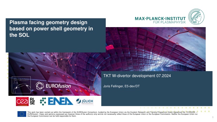
Plasma facing geometry design based on power shell geometry in the SOL TKT W-divertor development 07.2024 Joris Fellinger, E5-dev/DT This work has been carried out within the framework of the EUROfusion Consortium, funded by the European Union via the Euratom Research and Training Programme (Grant Agreement No 101052200 EUROfusion). Views and opinions expressed are however those of the author(s) only and do not necessarily reflect those of the European Union or the European Commission. Neither the European Union nor the European Commission can be held responsible for them. 1
Fundamental differences divertor baffle Divertor Baffle Plasma facing material Heat sink material Heat load requirement W-Cu Interface Connection type Interlayer W or W95NiFe Cu or CuCrZr 10 MW/m < 1-2 MW/m Cold contact sufficient Loose bolted connection allowed Graphite foil T @ 1 MW/m = 500 K Maximum W temperature Bolt design Perfect thermal bond required continuous 1 mm OFE-Cu T @ 10 MW/m = ~25 K Thermal expansion mismatch Interface stress singularity Key design concern CFC OFE Cu crack example 2
Design strategy divertor and baffle Calculate separatrix Independent of target geometry Divertor does not intersect core plasma Safe distance to inner envelop of separatrix Divertor intersects scrape of layer Intersection of outer envelope of separatrix Baffle does not intersect separatrix After optimisation of divertor position, baffles could be repositioned into shadowed area 3
Calculation of separatrix1 Calculate magnetic field with VMEC/Extender 200+ runs made by Joachim Geiger. VMEC model size (XS, S,M, L) iterated so that assumed LCFS agrees reasonably with Extender result Standard: beta 0 4.1%, Itor = -30 +20 kA High mirror: beta 0 4.0%, Itor = -20 +20 kA High Iota: beta 0 2.8%, Itor = -70 +20 kA Check results by evaluation of power deposition onto OP2 divertor 199/214 cases show >98% of particles deposited on first wall Calculate connection length Lc to OP2.2 target in EMC-lite-universal in toroidal section at 36 Infinite connection length: closed flux surfaces Short connection length: private flux region Intermediate connection length: points on the separatrix, depending on configuration: Lc= 300 500 m for high iota Lc= 600 960 m for standard and high mirror Remove target and trace points with intermediate connection length to find complete separatrix Number of toroidal turns needed to close the separatrix poloidally once depend on configuration n = 7 turns for high iota n = 65 turns for standard and high mirror Reduce number of points to 1 per voxel of 15x15 mm in 36 section Trace 0.1 toroidal turn (0-36 ) and store results for every 0.1 3D contour of power carrying layer in the SOL 4 Calculation approach adopted from approach by A. Kharwandikar
VMEC / Extender runs Config Beta[%] Itor [kA] 0.16% -30 -28 -26 -24 -22 -20 -18 -16 -14 -12 -10 -8 -6 -4 -2 0 2 4 6 8 10 12 14 16 18 20 0.65 -24 -18 -12 -6 0 6 12 18 24 1.32 -24 -18 -12 -6 0 6 12 18 24 Standard 2 -24 -18 -12 -6 0 6 12 18 24 2.69 -24 -18 -12 -6 0 6 12 18 24 3.4 -24 -18 -12 -6 0 6 12 18 24 4.13 -24 -18 -12 -6 0 6 12 18 24 0 -70 -60 -50 -40 -30 -20 -15 -10 -5 0 5 10 15 20 0.4 -20 -15 -10 -5 0 5 10 15 20 0.8 -20 -15 -10 -5 0 5 10 15 20 1.2 -20 -15 -10 -5 0 5 10 15 20 High Iota 1.6 -20 -15 -10 -5 0 5 10 15 20 2.0 -20 -15 -10 -5 0 5 10 15 20 2.4 -20 -15 -10 -5 0 5 10 15 20 2.8 -20 -15 -10 -5 0 5 10 15 20 0.0 -20 -15 -10 -5 0 5 10 15 20 1.0 -20 -15 -10 -5 0 5 10 15 20 High Mirror 2.0 -20 -15 -10 -5 0 5 10 15 20 3.0 -20 -15 -10 -5 0 5 10 15 20 5 4.0 -20 -15 -10 -5 0 5 10 15 20
Runs with less than 98% power on target Configuration Beta [%] 1.32 2.0 2.69 3.4 4.13 0 0.4 0.8 1.6 2 2.4 2.8 LCFS size S M S Itor [kA] -12 0 6 0 18 -10 Standard M XXS XXS M M M M M M M -15 -15 -10 -10 -15 -10 -10 High iota -15 -10 High iota with negative Itor is actually limiter case EMC3-lite run unreliable Error in power deposition for Standard not yet understood 6
Connection length in OP2: Standard All 500-700 m only 7
Connection length in OP2: High Iota All 300-450 m only 8
Trace selected points n toroidal turns All points (7k-100k points) Outliers / inliers Voxelized (0.5-1k points) High iota, beta = 0%, Itor= 0 kA 15x15 mm Asymmetry requires tracing in both directions 9
Tracing in 2 directions High iota, beta = 0%, Itor= 0 kA 10
Separatrix for any config with beta and Itor Standard beta variation toroidal current = 0 kA Standard beta = 0 % toroidal current variation -30 kA to +18 kA Standard beta = 3.4% toroidal current variation -24 kA to +24 kA High mirror beta variation toroidal current = 0 kA High mirror beta = 0 % toroidal current variation -20 kA to +20 kA High mirror beta = 4 % toroidal current variation -20 kA to +20 kA High iota beta variation toroidal current = 0 kA High iota beta = 0 % toroidal current variation -20 kA to +20 kA High iota beta = 2.8 % toroidal current variation -20 kA to +20 kA Standard / high mirror / high iota beta = 0 % toroidal current = 0 kA Standard / high mirror / high iota beta = 2.7 / 3.0 / 2.8 % toroidal current = 0 kA 11
Design limitations Provided the divertor intersects the outer coontour of the separatrix but does not intersect the LCFS poses a limit on the toroidal current that can be tolerated, especially at low beta Beta = 0 % Beta = 4 % Outside of separatrix @+15 kA < LCFS @-15 kA Outside of separatrix @+20 kA > LCFS @-20 kA 12
Toroidal current compensation by planar coils ( ) = / t 1 I I e , tor plasma Assuming I = 30 kA, = 10s Compensation by initial iota correction I0= -10 kA ( 1 ) = / ' AB t I I e bI t I 0 tor Adding transient planar coil current compensation With b = ~10 and ramp rate I AB= 30 A/s 13
Maximum toroidal current compensation Toroidal plasma current Itor develops approximately according to with decay constant = ~10s Planar coil currents IABcan compensate b Itor with b = ~10 Ramping speed of planar coil currents I AB = ~30 A/s Total toroidal current ( 0 1 tor AB I I e bI t I = ( ) = / t 1 I I e , tor plasma ) / ' t with I0 the initial toroidal current offset created by IAB,0 The toroidal current rate is I I bI = 10 30 10 = ' AB 3 [kA] I = ' / ' AB t e bI tor which can be fully compensated at t = 0 for Larger toroidal plasma current can be damped, peak value is reached at ' ln peak t I bI ' AB I bI = AB and results into = 1 ln ' AB I I bI I 0 peak Allowing a maximum toroidal current variation of I0 sets a limit for I of Power shell geometry variations can be limited to 10 kA for |I | < 30 kA ' AB + 2 I bI ' AB I 0 bI bI ' AB = + 1 ln = 6 2.4 + ' AB 2 3 e I I bI W I 0 1 0 14
