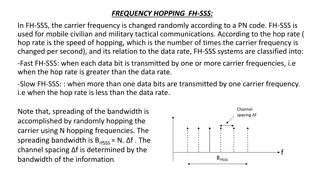
Analysis of Resonance Frequency and Performance of 560R Coils
Utilizing a setup with a 560R coil, a function generator, and an oscilloscope, the resonance frequency was examined at 6KHz. Peak voltage variances were observed between OK and NOK coils, with resonance frequencies appearing consistent. Further analysis revealed significant differences in peak-to-peak voltages across the coils when connected to a controller PCB. Elevated temperature data indicated resistance and inductance changes in the coils at room temperature and 80°C.

Uploaded on Sep 29, 2024 | 0 Views
Download Presentation

Please find below an Image/Link to download the presentation.
The content on the website is provided AS IS for your information and personal use only. It may not be sold, licensed, or shared on other websites without obtaining consent from the author. Download presentation by click this link. If you encounter any issues during the download, it is possible that the publisher has removed the file from their server.
E N D
Presentation Transcript
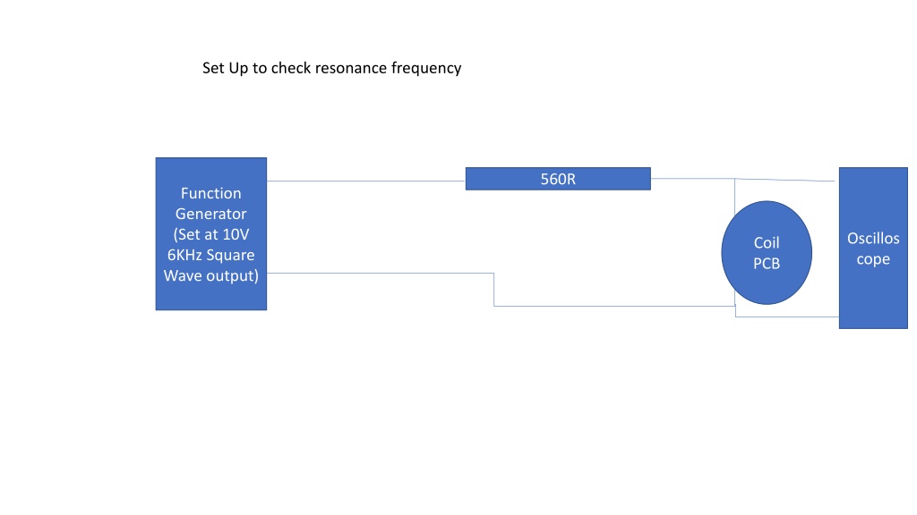
Set Up to check resonance frequency 560R Function Generator (Set at 10V 6KHz Square Wave output) Oscillos cope Coil PCB
NOK coil 560R 6KHZ Peak voltage seems to be lower compared to OK coil Peak voltage of OK coil : 2.605V Peak Voltage of NOK coil:2.155 Resonance frequency of both coil seems to be same
Waveforms of across coil when connected to controller PCB Difference in Peak-to-peak voltage is significant OK coil NOK coil
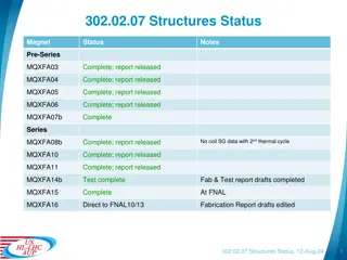
Elevated temperature data OK coil Nok coil R at RT R at 80 C 6.8R 7.06R 8.2R 8.7R Series L at RT (1KHZ) 15.2uH 14.7uH Series L at 80 C(1KHZ) 14.2uH 14.8uH