Understanding Earthing Transformers in Power Systems
Equipments in power systems operate under variable complex stresses, leading to unavoidable faults despite careful planning. Earthing transformers play a crucial role in reducing potential stresses during faults by providing a neutral grounding point. By effectively grounding circuits, these transformers enhance system safety, reliability, and fault protection. This article delves into the functions and benefits of earthing transformers, emphasizing their significance in maintaining a stable electrical infrastructure.

Download Presentation

Please find below an Image/Link to download the presentation.
The content on the website is provided AS IS for your information and personal use only. It may not be sold, licensed, or shared on other websites without obtaining consent from the author. Download presentation by click this link. If you encounter any issues during the download, it is possible that the publisher has removed the file from their server.
E N D
Presentation Transcript
Earthing Transformer PRESENTED BY PROF. VG PATEL VG PATEL Wednesday, July 17, 2024 1
TRANSFORMER ENCYCLOPAEDIA EARTHING TRANSFORMER INTRODUCTION Equipments connected to power systems and networks are operating under variable complex stresses in service. In power systems the faults are not avoidable even after taking utmost care at every stage of planning, designing, installing, commissioning and proper maintenance. It is a well-known fact that, the grounding of the circuit reduces potential stresses under conditions of faults. For a switchgear and protection engineer neutral grounding is very important because: The earth protection is based on the method of neutral earthing; and The system voltage during earth fault depends on neutral earthing. Wednesday, July 17, 2024 2 VG PATEL
TRANSFORMER ENCYCLOPAEDIA EARTHING TRANSFORMER The neutral point (star-point) is usually available at every voltage level from generator or transformer. In the absence of power transformer of suitable capacity, connection and design separate grounding transformer can be used. They are inductive devices intended primarily to provide a neutral point for grounding purpose (32.1.15 in AIEE Standard No. 32). They are interconnected star (Zigzag), connected. Factors like single winding, smaller capacity and economy factors preferred zigzag transformers compared to other two types. This article is restricted to zigzag type with oil filled transformers. Some of the major benefits of operating with grounded neutral systems are: star-delta and `T Wednesday, July 17, 2024 3 VG PATEL
TRANSFORMER ENCYCLOPAEDIA EARTHING TRANSFORMER improved reliability; improved fault protection; fewer faults; simplification of locating the faults; greater safety; limitation of transient over voltages; lower cost and less maintenance. Wednesday, July 17, 2024 4 VG PATEL
TRANSFORMER ENCYCLOPAEDIA EARTHING TRANSFORMER Earthing Transformer A Brief Account: A transformer is a device which electro magnetically transforms ac voltage from one level to another. An earthing transformer is a transformer primarily to provide a neutral point for grounding purpose. The sole duty of the grounding transformer is to pass ground current during earth fault and it carries no useful load. Desirable qualities of earthing transformer are low zero sequence impedance and low losses (no load losses). It is having a 5 limb construction. Wednesday, July 17, 2024 5 VG PATEL
TRANSFORMER ENCYCLOPAEDIA EARTHING TRANSFORMER Function of Earthing Transformers: Apart from providing easy path to ground current during earth fault, the following additional functions are also to be achieved: holding the neutral shift within limits; permitting the circulation of unbalanced load; to meet the current during line to earth fault; to earth the system; to provide single phase line to neutral load; and can be used with resistance / reactance / arc suppression coil. Wednesday, July 17, 2024 6 VG PATEL
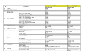
TRANSFORMER ENCYCLOPAEDIA EARTHING TRANSFORMER Comparison between Earthing and Power Transformers: The selection of any transformer mainly by two factors namely primary voltage and load. For an earthing transfor- mer, load is short duty or short time (only at the time of fault), normally from a few seconds to one minute. The features, which distinguish earthing transformers from power transfor- mers, are to be clearly understood before discussing on earthing transformer. The comparison of 2.29 MVA (short time) 2 MVA continuous duty power transformer details both in general as well as design parameters are given in the table below. Though in principle and operation both are same, yet they differ in so many respects. Salient differences and similarities enumerated for the benefits of power engineers. Wednesday, July 17, 2024 7 VG PATEL
TRANSFORMER ENCYCLOPAEDIA Comparison Characteristics EARTHING TRANSFORMER TRANSFORMER GENERAL PARAMETERS TRANSFORMER DESIGN PARAMETERS Earthi ng (2.29 MVA) 135 530 Power (2 MVA) Earthing Power Raising or lowering the supply voltages D* L* 240 725 To provide a neutral point for earthing Purpo se Core Frame (cm) A* 340 450 Wednesday, July 17, 2024 8 VG PATEL
TRANSFORMER ENCYCLOPAEDIA EARTHING TRANSFORMER Specif ication Weight of Copper (kg) IS:3151 IS:2026 240 686 Rating in kVA Short Time Continuou s Weight of Core (kg) 320 1360 High voltages (220 kV and above) Voltag e (in gener al) Upto 33 kV Flux Density (T) 1.65 1.66 Z or Y d (Not loaded) Vector Group DY11, Yd, Yy0, etc,. Maximum Current Density (A/mm2) 16 4.06 Wednesday, July 17, 2024 9 VG PATEL
TRANSFORMER ENCYCLOPAEDIA EARTHING TRANSFORMER No Short Circuit End Temperature ( C) 65 (10 155 (2 (Exists in Yd without loading) Essenti al Secondary Seconds ) Seconds ) One / Two / Three Bi- directio nal 2 second s Number of Windings No Load Loss (kW) One / Two 0.52 2.2 Direction of Power Flow Unidirectio nal Load Loss (kW) - 28.6 Short Circuit withstand duration 10 Impedance (%) seconds to 1 minute - 7.5 Wednesday, July 17, 2024 10 VG PATEL
TRANSFORMER ENCYCLOPAEDIA EARTHING TRANSFORMER Zero Sequence Impedance ( / Phase) No load lossesNo load losses and load losses Losses 5 - Magnitisin g Current Weight of Core and Winding (ton) Very less 0.8 2.25 Priority of Impedance Zero sequence impedance Short circuit impedance Weight of Oil (ton) 0.38 1.17 Depends on system from few hundred amperes to few thousand amperes Short Circuit Current Up to 25 times the normal current Total Weight (ton) 1.55 6.1 Wednesday, July 17, 2024 11 VG PATEL
TRANSFORMER ENCYCLOPAEDIA EARTHING TRANSFORMER Dimensio ns (Meter) Length 1.5 Breadth 0.7 3.05 Height 2.3 Leakage Resistance Little More 1.7 2.7 Voltage Regulation (by means of) Not Off circuit / No load Cost Factor (Present Cost) applicabl e Constant (in general) Not applicabl e 1 5 Constant / Variable / and Mixed Type of Voltage Regulation Required to Operate in Parallel Frequent Wednesday, July 17, 2024 12 VG PATEL
TRANSFORMER ENCYCLOPAEDIA EARTHING TRANSFORMER Transportation Short Circuit Temperature ( C) Harmonic Residuals Free Load Factor Insulation Efficiency Cost Road Road / Rail 250 250 Exist High Low Uniform More Less Uniform / Graded Less More Wednesday, July 17, 2024 13 VG PATEL
TRANSFORMER ENCYCLOPAEDIA EARTHING TRANSFORMER *D = Diameter; L = Limb Length and A = Centre Distance With the above comparison we can infer that for an earthing transformer: weights, losses, dimensions and cost factors are much lower; rise of oil / winding temperature is very less; higher specific loading and efficiency; and more significant factor is zero sequence impedance. Wednesday, July 17, 2024 14 VG PATEL
TRANSFORMER ENCYCLOPAEDIA EARTHING TRANSFORMER Significance of Zero Sequence Parameters: In symmetrical components, the positive sequence is one having normal phase sequence, the second is of negative sequence with reversed phase sequence and the third has no sequence called as a zero sequence are the important parameters. An earth fault is one that part of the current in the faulty phase return to the supply through the earth. This is due to a symmetrical component consisting of three single-phase currents one in each line and all being in phase. In general, the transformer impedance of the transformer is the main factor which influences application. The zero sequence impedance of standard earthing transformer can be calculated from the formula: 3 E Z = = s I n Wednesday, July 17, 2024 15 VG PATEL
TRANSFORMER ENCYCLOPAEDIA EARTHING TRANSFORMER Where Zs= Impedance in / Phase; E = Line to-line voltage in kV; and In = Neutral current in amperes. In certain system it is necessary to insert resistance or reactance to restrict the fault current. The zero sequence component of three line currents are compounded they will add together to produce a resultant called residue, whilst the positive and negative sequence components get cancelled in transformer. The magnetic field produced by zero sequence set of currents is radically different from those produced by negative or positive sequence currents and therefore zero sequence impedance is generally very different from positive and negative impedances. Zero sequence reactance is equal to or less than positive sequence and it depends on the form of core construction and disposition of the windings. Wednesday, July 17, 2024 16 VG PATEL
TRANSFORMER ENCYCLOPAEDIA EARTHING TRANSFORMER Why Interconnected Star Winding is used? Purpose to establish a suitable ground path can be achieved with the help of three pairs of concentric coils connected to oppose ampere-turns. As the fluxes oppose, the transformer takes very small magnetizing current during normal condition. Lines of force enclo- sing both coils on one limb are therefore impossible. The earth fault current finds little impedance. This connection has unique characteristics and preferred to other types of neutral deriving transformers. Wednesday, July 17, 2024 17 VG PATEL
TRANSFORMER ENCYCLOPAEDIA EARTHING TRANSFORMER The main features are: winding has much lower impedance to zero sequence currents; free from harmonic residuals; stable neutral can be obtained; most economical and practical; can be used with three phase system without secondary winding; permitting single phase line to neutral load; can be economically used with resistance/reactance/are suppression coil; equivalent kVA is approximately 57.5% of star-delta transformer; avoidance of undesirable stresses in the insulation; can be used with either delta or star connected windings to feed desired load; it keeps zero sequence impedance constant even auxiliary winding under load; and fault current is not reflected on to the secondary side (auxiliary winding). From the above, it is very clear that, the inter connected star winding can be utilized as earthing transformer or power transformer or in combination depending upon the requirement. Wednesday, July 17, 2024 18 VG PATEL
TRANSFORMER ENCYCLOPAEDIA EARTHING TRANSFORMER Rating and Inter Related Parameters of Earthing Transformer: The earthing transformers are of short time rating (Ten seconds to one minute). The rating of earthing transformer is entirely different from power transformers. Power transformers are designed to carry total load continuously, whilst the earthing transformers carries no load and supplies current only if one of the lines becomes grounded. It is usual to specify the single-phase earth fault current that the earthing transformer must carry for sufficient time. Since it is almost working on no-load, dictates to have low iron losses. Because of short time device, its size and cost are less than that of continuous duty transformer of equal kVA rating. The kVA rating of a three phase earthing transformer or a bank is the product of normal line to neutral voltage (kV) and the neutral or ground amperes that the transformer is designed to carry under fault conditions for a specified time. In figure 1, if 3I is the total earth fault current and V is the line voltage, the earthing transformer short time rating is equal to root 3 VI. 3 VI Wednesday, July 17, 2024 19 VG PATEL
TRANSFORMER ENCYCLOPAEDIA EARTHING TRANSFORMER When specifying the rating of an earthing transformer , the important parameters are: Voltage: The line-to-line voltage of the system; Current: The maximum neutral current to carry for a specified duration. In grounded system it is based on type of grounding. Depending on their duration, several rates short time currents may be specified when a load is to be connected to secondary winding; Wednesday, July 17, 2024 20 VG PATEL
TRANSFORMER ENCYCLOPAEDIA EARTHING TRANSFORMER V/ 3 V/? 3 V/ V/? 3 3 V/? 3 V/3 V/ V V 3 V V/ 3 V W U N I I I 3I V/3 V/3 V/3 V/3 V/3 V/3 I I I Fig. 1: Three-Phase Inter Connected Star Neutral Earthing Transformer Wednesday, July 17, 2024 21 VG PATEL
TRANSFORMER ENCYCLOPAEDIA EARTHING TRANSFORMER Time: Designed to carry rated for short time duration of 10 seconds to 60 seconds. Depending upon the time setting of the protective gear on the system and the location of the transformer. Earthing transformer time is 10 seconds for protection and for feeder it is 60 seconds. Reactance: This quality is a function of the initial symmetrical three-phase short circuit KVA. It also based on the type of grounding and type of application of lightning arrester and transient over voltages. Wednesday, July 17, 2024 22 VG PATEL
TRANSFORMER ENCYCLOPAEDIA EARTHING TRANSFORMER Major Design, Constructional and Manufacturing Features: Desired electrical parameters of the earthing transformer are to be achieved by verifying the calculations based on electrical, mechanical and thermal computations. Such as the required electrical strength, mechanical ruggedness, dynamic and thermal resistance of the windings in the event of short circuit are to be solved carefully at the design stage. When designed as an earthing transformer it is usually manufactured as an autotransformer (inter star). Wednesday, July 17, 2024 23 VG PATEL
TRANSFORMER ENCYCLOPAEDIA EARTHING TRANSFORMER Wednesday, July 17, 2024 24 VG PATEL
TRANSFORMER ENCYCLOPAEDIA EARTHING TRANSFORMER Wednesday, July 17, 2024 25 VG PATEL
TRANSFORMER ENCYCLOPAEDIA EARTHING TRANSFORMER The following brief details refers to core type oil filled transformer with cylindrical windings for zigzag with or without auxiliary winding which are popular all over the world. The core of such transformer is built in the same manner as that of transformer with the only difference that instead of two windings per limb will have single winding per limb which is divided into two equal portions and connected as shown in figure 2. The current flowing are in opposition, thereby undesirable harmonics are avoided. The choice of the winding configurations is dictated by zero sequence impedance in single winding. With on auxiliary by both zero sequence and short-circuit impedance. Auxiliary winding may be used continuously to supply station auxiliaries. Wednesday, July 17, 2024 26 VG PATEL
TRANSFORMER ENCYCLOPAEDIA EARTHING TRANSFORMER The type of windings may be either multilayer, helical or disc windings mainly based on current and voltages. Generally, voltages of these transformers are upto 33 kV and currents up to several kilo-amperes based on system requirements. Figure shows the different configurations and is required to meet both zero sequence impedance and short circuit impedance. Magnetic and electric loadings are similar to power transformer. The basis of ultimate temperature rise calculation is that all the heat stored in the copper without dissipation to insulating media or surroundings. According to standards, end temperature rise depends on the duration of the fault, ultimate being 250 C for copper winding in oil. For continuous rating, calculation is similar to normal power transformers. Insulation design is mainly based on dielectric constants of paper and oil. Wednesday, July 17, 2024 27 VG PATEL
TRANSFORMER ENCYCLOPAEDIA EARTHING TRANSFORMER The ideal stress distribution can be obtained through field plotting by finite element method (FEM). Because of frequent short circuit capability, remedial measures like strengthening of the coils, proper materials, and avoidance of magnetic asymme- try are to be observed. Since, only iron losses are to be dissi- pated, the tank dissipation is adequate in majority of the cases. With auxiliary loading proper care is necessary in respect of heat dissipation for the reliability of the transformers. In case of earthing transformers for industrial applications and for heavily polluted atmosphere, demands bushings of higher creepage distances to avoid frequent flashovers. Further, external surfaces are to be painted with epoxy base paint. Testing of these transformers is in accordance with National and Inter- national standards to verify various parameters. Transportation of these transformers is similar to small power transformers on road. Wednesday, July 17, 2024 28 VG PATEL
TRANSFORMER ENCYCLOPAEDIA OPEN FORUM Wednesday, July 17, 2024 29
TRANSFORMER ENCYCLOPAEDIA THANQ Wednesday, July 17, 2024 30