Designing Low-Pass Filter for Square Wave Harmonic Suppression

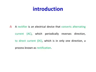
This tutorial discusses the design of a low-pass filter to suppress harmonics in the output of a square wave signal. The goal is to achieve at least 32 dB attenuation of any harmonics relative to the fundamental sinusoid at 5 kHz. The solution involves analyzing the square wave, determining the necessary filter specifications, and designing a fourth-order Butterworth low-pass filter with a cutoff frequency at 7.5 kHz. The transfer function of the filter and key calculations are provided to achieve the desired harmonic suppression.

Download Presentation

Please find below an Image/Link to download the presentation.
The content on the website is provided AS IS for your information and personal use only. It may not be sold, licensed, or shared on other websites without obtaining consent from the author. Download presentation by click this link. If you encounter any issues during the download, it is possible that the publisher has removed the file from their server.
E N D
Presentation Transcript
EE 3TR4 Tutorial 1: Fourier Series TA: Wei Jiang Professor: Dr. Shiva Kumar Jan. 27, 2021 School of Biomedical Engineering McMaster University, Hamilton, ON L8S 4K1, Canada Email: jiangw35@mcmaster.ca
Tutorial 1: Fourier Series Question: We are given a square wave whose period is 0.2 ms. Design a low- pass filter so that any harmonics in the output are at least 32 dB below the fundamental sinusoid at 5 kHz. T T0 LPF 2
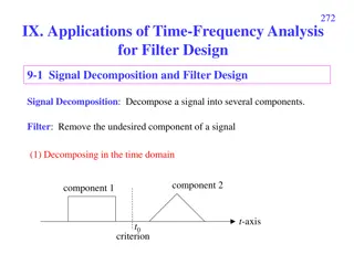
Analysis One Example of Periodic Square Wave Superimposed sinusoidal waves 3 https://web.sonoma.edu/esee/courses/ee442/lectures/lect04_fourier.pdf
Solution: The input is a periodic pulse train gp(t) Period = ?? Pulse Width = ? A = 1 For a square wave (50% duty cycle): ??= 2 ? gp(t) A t ?? ? ? ? ? ? ?? ? 4
Solution: (cont.) Pulse train in the frequency domain ??= ?? ???? ?? ,????? ? = For a square wave (50% duty cycle) ? =? ????? C0= 0.5, C1= 0.3183, C3= -0.1061, C5= 0.0637 Even harmonics are zeros since ???? ??????? ? = ? ? ?? ?,??=? ? ?, 5
Solution: (cont.) Therefore, we need to design a filter to make sure ?? ????? ( ?? Note that ?? is neither a fundamental frequency nor a higher order harmonic. The corresponding frequency of ?? is 0, which means that it is a DC component that can be blocked by a capacitor (AC-coupling). Let s examine the value of ?? and ?? For the square wave: ???)- ?? ????? ( ?? out) > 32 dB ?? ?????(?? According to the Specification, the ratio should be at least 32 dB, therefore the filter should provide additional 22.46 dB attenuation 32 9.54 = 22.46 ?.???? ?.???? ??) = ?? ????? = ?.?? ?? 6
Solution: (cont.) Filter design Fundamental component (5 kHz) is within the passband Higher order harmonics (15 kHz and above) are outside the passband Let us try a fourth-order Butterworth low pass filter with a cutoff frequency at 7.5 kHz The transfer function of a fourth-order Butterworth low pass filter, normalized to a cutoff frequency of 1 rad/s is given by ? ?(?) = (??+ ?.???? + ?)(??+ ?.???? + ?) This function can be found in the textbook of filter theory, its plot is shown in Fig.1 7
Solution: (cont.) Cutoff frequency: 1 rad/s -3 dB Fig.1 8
Solution: (cont.) We wish to design the filter with a cutoff frequency of 7.5 kHz. Then, the frequency axis was multiplied by 7.5 kHz. The desired frequency response is shown in Fig. 2 Note that ??(??? ?.? ???) = -3 dB The response at 15 kHz ??(??? ?? ???) = -24.12 dB Fig.2 9
Solution: (cont.) We can use the normalized frequency response as shown in the transfer function. ? ?(?) = (??+ ?.???? + ?)(??+ ?.???? + ?) To find the frequency response at any real frequency f, we need to normalize f to the cutoff frequency (7.5 kHz). For example, when f = 15 kHz, the normalized frequency is 15/7.5 = 2. Therefore, the frequency response at 15 kHz is ?? ????? ? ? ?=?? ? = ?? ????? ???+ ?.??? ?? + ? ???+ ?.??? ?? + ? = ??.? ?? Attenuation at 15 kHz is 24.1 dB, which is greater than the required 22.46 dB. For any real frequency response, just need to calculate the normalized frequency by dividing the cutoff frequency. 10
In order to meet the requirement, we need to check the attenuation at 5 kHz. If the attenuation at 5 kHz is smaller then 1.64 dB (24.1-22.46 =1.64), then the designed filter meets the Specification. 11
Solution: (cont.) Calculation the frequency response at 5 kHz Normalized frequency 5 k/7.5 k = 2/3 ?? ????? ? ? ?=?(?/?) ? = ?? ????? ?(?/?)?+ ?.??? ?(?/?) + ? ?(?/?)?+ ?.??? ?(?/?) + ? = ?.???? ?? The attenuation is quite small; thus, the designed filter meets the requirements. Note that All even harmonics are zeros All odd harmonics higher than the 3rd harmonic are attenuated more than the 3rd one. Attenuation of the 5th harmonic (25 kHz): ?? ????? ? ? ?=?(?? ??? ?? ?.??)= -41 dB 12
Thank you! Q&A 13 13
BACKUP SLIDES 14 14
Cn C0=0.5 C1=0.3183 C5=0.0637 C3= -0.1061 18


")
")
")
")
")
")

")