Introduction to Digital Filter Design in Signal Processing

Discrete time filters play a crucial role in signal processing, with finite impulse response (FIR) and infinite impulse response (IIR) systems being two key types. FIR filters have finite duration unit sample responses, while IIR filters have infinite duration responses. FIR filters are implemented without feedback, IIR filters with feedback. Designing FIR filters involves selecting window types, determining cutoff and stop-band requirements, and finding the impulse response. The process involves converting analog specifications to digital specifications for A/D-D/A structures based on sampling rates. Common window functions used in FIR filter design include Rectangular, Bartlett, Hanning, Hamming, and Blackman.

Uploaded on Aug 06, 2024 | 1 Views
Download Presentation

Please find below an Image/Link to download the presentation.
The content on the website is provided AS IS for your information and personal use only. It may not be sold, licensed, or shared on other websites without obtaining consent from the author. Download presentation by click this link. If you encounter any issues during the download, it is possible that the publisher has removed the file from their server.
E N D
Presentation Transcript
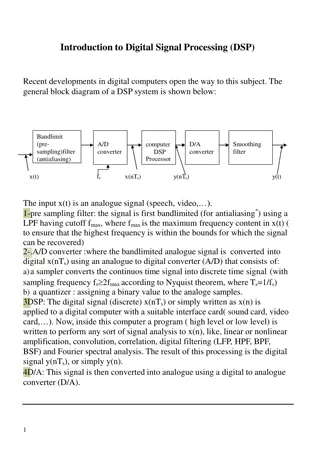
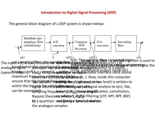
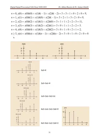
Signal Processing Lec. 9 Digital Filter 10.1 Introduction: Adiscrete time filter takes a discrete time input sequence x(n) and produces a discrete time output sequence y(n). Aspecial class of a discrete time shift-invariant system can be characterized by a unit sample response h(n), a system function H(Z), or difference equation. ( 10.1) .. .. ( 10.2) If unit sample response h(n) is of finite duration, the system is said to be a finite impulse response (FIR) system. Eq. (9.1) represents FIR system if a 0 and a = 0 for 0 k k=1, 2,..N. If unit sample response h(n) is of infinite duration, the system is said to be an infinite impulse response (IIR) system. IIR filter is usually implemented by recursive realization (is one in which the present value of the output depends on both the input present and or past values), i.e., with feedback. FIR filter is usually implemented by either a nonrecursive realization (without feedback) or an FFT realization. Asst. Lec. Haraa Raheem Page 1
Signal Processing Lec. 9 10. 2 Acomparison between FIR and IIR filters: 10.3 Design of FIR filters using Window method Design procedure for an FIR filter Requirements: k , w , k , and w represents the cutoff and stop-band requirements for digital 1 1 2 2 filters. 1. FromTable (1), select the window type such that the stop-band gain exceeds k 2. Selects the number of points in the window, 2 3. Select and w , where : c w = w , and = ( N 1 ) /2 c 1 4. Find h(n) from eq. (1) using the specified window type and Table (2) . Asst. Lec. Haraa Raheem Page 2
Signal Processing Lec. 9 (1) where w(n) designates the window function. Common window functions used in the FIR filter design are as follows: Asst. Lec. Haraa Raheem Page 3
Signal Processing Lec. 9 5. If the filter is to be used in A/D- H(Z) D/A structure, the equivalent analog specifications must be converted to digital specifications. For analog critical frequencies, , the corresponding digital specifications using a sampling rate of 1 / T i samples /sec. ; w = T i i Table (1) Design table for FIR LPF Transition Width (w ) Minimum stop-band attenuation Window t Rectangular 4 / N 21 dB Bartlett 8 / N 25 dB Hanning 8 / N 44 dB Hamming 8 / N 53 dB Blackman 12 / N 74 dB Asst. Lec. Haraa Raheem Page 4
Signal Processing Lec. 9 Table (2) h (n) and h ( ) for LPF, HPF, BPF, and BS d d Asst. Lec. Haraa Raheem Page 5
Signal Processing Lec. 9 Example (1): Design a LP digital filter to be used in A/D- H(Z) D/A structure that will have a 3 dB cutoff of 30 rad / sec. and an attenuation of 50 dB at 45 rad/sec. The filter is required to have linear phase. The system will use a sampling rate of 100 samples/sec. Using eq. for wHamand the valueof h (n) from Table (2) to find h(n): 4. d H.W: We want to design a Low Pass FIR Filter with the following characteristics: Passband 10kHz, Stopband 11kHz, with attenuation of 50dB, Sampling frequency 44kHz .Determine the causal impulse response h(n), and an expression for the phase within the passband. Asst. Lec. Haraa Raheem Page 6
Signal Processing Lec. 9 3.Design of FIR filters using FourierTransform method Design procedure for an FIR filter 1.Calculating the normalized cutoff frequency c=2 *fcTs 2. calculating 2M+1=No. of tap 3. calculating h(n) from table (3) to achieve the 2M + 1. Then we delay the truncated impulse response h(n) by M samples to yield the following causal FIR filter: where the delay operation is given by table (3) summary of ideal impulse responses for standard fir filters. Asst. Lec. Haraa Raheem Page 7
Signal Processing Lec. 9 EX: Calculate the filter coefficients for a 3-tap FIR lowpass filter with a cutoff frequency of 800 Hz and a sampling rate of 8,000 Hz using the Fourier transform method. AND Determine the transfer function and difference equation of the designed FIR system. SOL: The computed filter coefficients via the previous expression are listed as: Thus delaying h(n) by M =1 sample The transfer function is achieved as: Asst. Lec. Haraa Raheem Page 8
Signal Processing Lec. 9 10.4 Techniques for designing H(Z) for IIR filter There are a variety of methods that can be used to design digital filters as we will see in this section and the next. One commonly used method is to use the analog filter approximation functions that have already been developed and simply translate them in a way that will make them usable for discrete-time systems. 6.4.1 IMPULSE RESPONSE INVARIANT DESIGN The impulse response invariant design method (or impulse invariant transformation) is based on creating a digital filter with an impulse response that is a sampled version of the impulse response of the analog filter. We first start with an analog filter s transfer function H(s), and by using the inverse Laplace transform, we determine the system s continuous impulse response h(t). We next sample that response to determine the system s discrete-time impulse response h(nT). We then take the z-transform of this sampled impulse response to find the discrete-time transfer function H(z). the procedure of this transformation include many steps: If h (t) represents the response of an analog filter to a unit impulse (t), then the unit a sample response of a discrete-time filter used in an A/D-H(Z)-D/A structure is selected to be the sampled version of h(n). If an analog filter with system function H (S) is given, the corresponding impulse invariant a design filter has Asst. Lec. Haraa Raheem Page 9
Signal Processing Lec. 9 Impulse invariant design method Ex : Assume that we wish to convert the following continuous-time transfer function to a discrete-time transfer function using the impulse invariant transformation method: Solution: We first use basic partial fraction expansion techniques to write the transfer function in a form suitable for inverse transformation: Then recognizing the Laplace transform pair we can easily find the impulse response as Asst. Lec. Haraa Raheem Page 10
Signal Processing Lec. 9 we simply replace every t with nT to denote the nth sample at intervals of T: This expression can be rewritten in a form that more clearly indicates the exponential relationship of n: Now we use the z-transform And, finally, we can combine the terms over a common denominator to produce the final result, which can be simplified once a value of the sampling period T is chosen: As can be verified in the example, for every term in the analog transfer function of the form shown in Ex , there is a term created in the digital transfer function of the form shown in : Ex: Determine the impulse invariant digital filter for a second-order Butterworth approximation function, as shown below. Notice that H(s) is normalized and therefore has a passband edge frequency of 1 rad/sec or (1/2 Hz). Determine the differences that result from choosing sampling periods of T = 1.0 sec and T = 0.1 sec. Asst. Lec. Haraa Raheem Page 11
Signal Processing Lec. 9 Solution: We can first factor the analog transfer function and use partial fraction expansion to determine The digital transfer function can then be determined H.W : Consider the following Laplace transfer function: Determine H(z) using the impulse invariant method if the sampling rate fs =10 Hz. Asst. Lec. Haraa Raheem Page 12