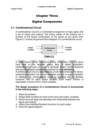
Understanding Standard Combinational Modules in Digital Design

Introduction to standard combinational modules such as decoders, encoders, multiplexers (Mux), demultiplexers (DeMux), shifters, adders, and multipliers. Exploring their behaviors, logic, and applications in signal transport, data processing, and address manipulation. Detailed explanation of how decoders decode addresses, encoders encode addresses, Mux selects data by address, DeMux directs data by address, shifters shift bit location, and operators like adders and multipliers work in binary arithmetic. Further insights into the interconnection of processors, arbiters, memory banks, and various modules to achieve efficient data handling.

Download Presentation

Please find below an Image/Link to download the presentation.
The content on the website is provided AS IS for your information and personal use only. It may not be sold, licensed, or shared on other websites without obtaining consent from the author. Download presentation by click this link. If you encounter any issues during the download, it is possible that the publisher has removed the file from their server.
E N D
Presentation Transcript
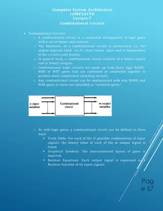
CSE 140 Lecture 11 Standard Combinational Modules CK Cheng CSE Dept. UC San Diego 1
Part III - Standard Combinational Modules Introduction Decoder Behavior, Logic, Usage Encoder Multiplexer (Mux) Behavior, Logic, Usage Demultiplexier (DeMux) 2
Part III - Standard Combinational Modules Signal Transport Decoder: Decode address Encoder: Encode address Multiplexer (Mux): Select data by address Demultiplexier (DeMux): Direct data by address Shifter: Shift bit location Data Operator Adder: Add two binary numbers Multiplier: Multiply two binary numbers 3
Interconnect: Decoder, Encoder, Mux, DeMux Processors Arbiter Data 1 Mux Memory Bank P1 Data Address 1 P2 Demux n-m Mux Address 2 Address n m 2m Address k Decoder Data k Decoder: Decode the address to assert the addressed device Mux: Select the inputs according to the index addressed by the control signals Pk 4
1. Decoder Definition Logic Diagram Application (Universal Set) Tree of Decoders 5
iClicker: Decoder Definition A. A device that decodes B. An electronic device that converts signals from one form to another C. A machine that converts a coded text into ordinary language D. A device or program that translates encoded data into its original format E. All of the above 6
Decoder Definition: A digital module that converts a binary address to the assertion of the addressed device E (enable) y0 y1 . . 0 1 2 3 4 5 6 7 I0 I1 I2 0 1 2 y7 n to 2n decoder function: 2n outputs 23= 8 n inputs n= 3 yi = 1 if E= 1 & (I2, I1, I0 ) = i yi= 0 otherwise 7
1. Decoder: Definition N inputs, 2N outputs One-hot outputs: only one output HIGH at most E 2:4 Decoder 11 Y3 Y2 Y1 Y0 A1 A0 10 01 00 E= 1 A1 A0 Y3 Y2 0 0 1 0 Y1 0 1 0 0 Y0 1 0 0 0 0 0 1 1 0 1 0 1 0 0 0 1 8
1. Decoder: Definition iClicker: A 3-input decoder has how many outputs? A. 2 outputs B. 4 outputs C. 8 outputs D. 10 outputs E 9
Decoder Definition iClicker: For a 3-input decoder, suppose (E,I2,I1,I0)=(1,0,0,0), then (y7,y6, , y0) is equal to: A. (00000000) B. (00000001) C. (00000010) D. (01000000) E. (10000000) E (enable) y0 y1 . . 0 1 2 3 4 5 6 7 I0 I1 I2 0 1 2 y7 8 outputs 3 inputs 10
Decoder: Logic Diagram (Inside a decoder) y0 = 1 if (A1, A0 ) = (0,0) & En = 1 En yi = mi En 2:4 Decoder A0 11 Y3 Y2 Y1 Y0 A1 y0 A1 A0 10 01 00 y1 . . A1 A0 Y3 Y2 0 0 1 0 Y1 0 1 0 0 Y0 1 0 0 0 0 0 1 1 0 1 0 1 0 0 0 1 y3 y3 = A1A0En 11
1. Decoder: Definition PI Q: What is the output Y3:0 of the 2:4 decoder for (A1, A0) = (1,0)? 2:4 Decoder A. (1, 1, 0, 0 ) B. (1, 0, 1, 1) C. (0, 0, 1, 0) D. (0, 1, 0, 0) 11 Y3 Y2 Y1 Y0 A1 A0 10 01 00 12
Decoder Application: universal set {Decoder, OR} Example: Implement the following functions with a 3-input decoder and OR gates. i) f1(a,b,c) = m(1,2,4) ii) f2(a,b,c) = m(2,3), iii) f3(a,b,c) = m(0,5,6) 13
Decoder Application: universal set {Decoder, OR} Decoder produces minterms when E=1. We can use an OR gate to collect the minterms to cover the On-set. For the Don t Care-Set, we can just ignore the terms. 14
Decoder Application: universal set {Decoder, OR} Example: Implement functions i)f1(a,b,c) = m(1,2,4) + d(0,5), ii)f2(a,b,c) = m(2,3) + d(1,4), iii)f3(a,b,c) = m(0,5,6) y1 y2 y4 with a 3-input decoder and OR gates. f1 y2 E=1 y3 f2 y0 . . y7 0 1 2 3 4 5 6 7 I0 I1 I2 c b a y0 y5 y6 f3 15
Decoders OR minterms E=1 2:4 Decoder Minterm 11 AB AB AB AB A B 10 01 00 Y = AB + AB = A B Y 16
Tree of Decoders: Scale up the size of the decoders using a tree structure Implement a 4-24 decoder with 3-23 decoders. y0 . 0 1 2 3 4 5 6 7 d c b I0 I1 I2 y7 y8 . 0 1 2 3 4 5 6 7 I0 I1 I2 y15 a 17
Tree of Decoders Implement a 6-26 decoder with 3-23 decoders. E y0 E I2, I1, I0 D0 y7 y8 I5, I4, I3 I2, I1, I0 D1 y15 y56 I2, I1, I0 D7 y63 18
PI Q: A four variable switching function f(a,b,c,d) can be implemented using which of the following? A. 1:2 decoders and OR gates B. 2:4 decoders and OR gates C. 3:8 decoders and OR gates D. All of the above E. None of the above 19
2. Encoder Definition Logic Diagram Priority Encoder 20
iClicker: Definition of Encoder A. Any program, circuit or algorithm which encodes B. In digital audio technology, an encoder is a program that converts an audio WAV file into an MP3 file C. A device that convert a message from plain text into code D. A circuit that is used to convert between digital video and analog video E. All of the above 21
Encoder Definition: A digital module that converts the assertion of a device to the binary address of the device. E I2n-1 I0 yn-1 y0 Encoder Description: A E At most one Ii = 1. (yn-1,.., y0 ) = i if Ii = 1 & = 1 (yn-1,.., y0 ) = 0 otherwise. A = 1 if E = 1 and one i s.t. Ii = 1 A = 0 otherwise. I0 0 1 2 3 4 5 6 7 y0 y1 y2 0 1 2 I7 3 outputs A 8 inputs 22
Encoder: Logic Diagram En En y0 y1 I2 I3 I6 I7 I1 I3 I5 I7 En En y2 I4 I5 I6 I7 A I0 I1 .. I6 I7 23
Priority Encoder: E I0 0 y0 0 1 2 y1 3 1 I3 Eo Gs 24
Priority Encoder: Definition Description: Input (I2n-1, , I0), Output (yn-1 , ,,y0) (yn-1 , ,,y0) = i if Ii = 1 & E = 1 & Ik = 0 for all k > i (high bit priority) or for all k< i (low bit priority). E Eo = 1 if E = 1 & Ii = 0 for all i, Gs = 1 if E = 1 & i s.t. Ii = 1. (Gs is like A, and Eo passes on enable). I0 0 1 2 3 4 5 6 7 y0 y1 y2 E 0 1 2 I7 Eo Gs 25
Priority Encoder: Implement a 32-input priority encoder w/ 8 input priority encoders (high bit priority). E I31-24 y32, y31, y30 Gs Eo I25-16 y22, y21, y20 Gs Eo I15-8 y12, y11, y10 Gs Eo I7-0 y02, y01, y00 Gs Eo 26


")


")