Verilog FF Circuit Examples & Assignments Overview

Delve into Verilog FF circuit examples such as Gated D Latch and D Flip-Flop. Understand blocking and non-blocking assignments, their differences, and practical implications. Learn when to use each assignment method in Verilog design for combinational always blocks.

Download Presentation

Please find below an Image/Link to download the presentation.
The content on the website is provided AS IS for your information and personal use only. It may not be sold, licensed, or shared on other websites without obtaining consent from the author. Download presentation by click this link. If you encounter any issues during the download, it is possible that the publisher has removed the file from their server.
E N D
Presentation Transcript
Supplement on Verilog FF circuit examples Based on Fundamentals of Digital Logic with Verilog Design, Fundamentals of Logic Design, and MIT slides Chung-Ho Chen 1
A Gated D Latch Whenever D or Clk changes, Q changes. module D_latch (D, Clk, Q); input D, Clk; output reg Q; Clk Not a real register!! A Verilog register needed because of assignment in always block Clk always @(D, Clk) if (Clk) Q = D; Q = D if Clk = 1, the Verilog compiler assumes that the value of Q caused by the if must be maintained when Clk is not equal to 1. This implies that a memory, a latch is instantiated. endmodule 2
A D Flip-Flop negedge posedge module flipflop (D, Clk, Q); input D, Clk; output reg Q; always @(posedge Clk) Q = D; endmodule 3
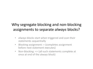
Blocking assignment: evaluation and assignment are immediate assignment are immediate evaluation and Blocking assignment: always @ (a or b or c) begin x = a | b; y = a ^ b ^ c; 2. evaluate a ^ b^c, and assign result to y end 1. evaluate a | b, and assign result to x 4
Non-Blocking assignment Nonblocking assignment: all assignments deferred until all right-hand sides have been evaluated (end of simulation timestep) always @ (a or b or c) begin x <= a | b; 1. evaluate a | b, but defer assignment of x y <= a ^ b ^ c; 2. evaluate a ^ b^c, but defer assignment of y end 3. assign x, y with their new values Non-blocking assignment is 2-step processes: Step 1: Evaluate the RHS Step 2: Update the LHS Sometimes, as above, blocking and non-blocking produce the same result. Sometimes, not! 5
Use blocking assignment for combinational always blocks always @ (input a, b, c, output reg x, y) begin x = a & b; y = x | c; end always @ (input a, b, c, output reg x, y) begin x <= a & b; y <= x | c; end Non-Blocking behavior Initial condition a changes; always block triggered x = a & b; y = x | c; a b c x y 1 1 0 1 1 0 1 0 1 1 0 1 0 1 1 x<=0, new value for x is 0, but not assigned yet. 0 1 0 1 1 x<=0, y <=1 0 1 0 0 1 assignment completion This is incorrect! 7
Verilog Simulation Behavior Always blocks and assign statements execute in parallel Signals in the sensitivity list (@(..)) trigger the always blocks. assign triggered when RHS signal changes. All non-blocking assignment statements in an always block are evaluated using the values that the variables have when the always block is entered. That is, a given variable has the same value for all statements in the block. The result of each non-blocking assignment is not seen until the end of the always block. 8
Blocking Assignment // blocking assignment here, so at each rising clock edge, Q1=D, after that, Q2 = Q1, finally Q2=Q1=D This implies a circuit below: module two-FFs (D, Clock, Q1, Q2); input D, Clock; output reg Q1, Q2; always @(posedge Clock) begin Q1 = D; Q2 = Q1; end Q D D Q 1 Clock Q endmodule Q D Q 2 Q 9
Non-Blocking Assignment // at the rising clock edge, Q1 and Q2 simultaneously receive the old values of D, and Q1. module two-FFs (D, Clock, Q1, Q2); input D, Clock; output reg Q1, Q2; always @(posedge Clock) begin Q1 <= D; Q2 <= Q1; end // at the end of always block, Q1 and Q2 change to a new value concurrently. endmodule Q 1 Q 2 D Q Q D D Clock Q Q 10
D-FF with Asynchronous Reset (Clear) module flipflop (D, Clock, ClrN, Q); input D, Clock, ClrN; output reg Q; always @(negedge ClrN, posedge Clock) if (!ClrN) // if clear, then, Q <= 0; else // normal update Q <= D; endmodule What about both? PreN and ClrN 11
D-FF with Synchronous Reset module flipflop (D, Clock, ClrN, Q); input D, Clock, ClrN; output reg Q; always @(posedge Clock) if (!ClrN) // if clear, then, Q <= 0; else // normal update Q <= D; endmodule What about both? PreN and ClrN 12
n-bit register module regn (D, Clock, Resetn, Q); parameter n = 16; input [n-1:0] D; input Clock, Resetn; output reg [n-1:0] Q; Naming: Resetn 16 bits here Asynchronous clear always @(negedge Resetn, posedge Clock) if (!Resetn) Q <= 0; else Q <= D; endmodule 13
Shift Register module shift4 (R, L, Din, Clock, Q); input [3:0] R; input L, Din, Clock; output reg [3:0] Q; L: load register with input. Non-blocking statements, so that value before clock edge is shifted into the destination bit, at the end of the always block. always @(posedge Clock) if (L) Q <= R; else begin Q[0] <= Q[1]; Q[1] <= Q[2]; Q[2] <= Q[3]; Q[3] <= Din; end Q3 Q2 Q1 Q0 D Din DFF 3 DFF 2 DFF 0 DFF 3 endmodule 14
Up Counter with enable module upcount (Resetn, Clock, E, Q); input Resetn, Clock, E; output reg [3:0] Q; If not reset, at rising edge and enabled, increment the counter by 1 always @(negedge Resetn, posedge Clock) if (!Resetn) Q <= 0; else if (E) Q <= Q + 1; endmodule 15
Up/down Counter with enable module UDcount (R, Clock, L, E, up_down, Q); parameter n = 8; input [n-1:0] R; input Clock, L, E, up_down; output reg [n-1:0] Q; always @(posedge Clock) if (L) Q <= R; else if (E) Q <= Q + (up_down ? 1 : -1); Q <= Q+1 Q <= Q-1 endmodule 16
FF with an enable module rege (D, Clock, Resetn, E, Q); input D, Clock, Resetn, E; output reg Q; always @(posedge Clock, negedge Resetn) if (Resetn == 0) Q <= 0; else if (E) Q <= D; endmodule 17


")