CASE IH AXIAL-FLOW 7230 Combine Service Repair Manual Instant Download (PIN YDG222001 and above)
Please open the website below to get the complete manualnn//

Download Presentation

Please find below an Image/Link to download the presentation.
The content on the website is provided AS IS for your information and personal use only. It may not be sold, licensed, or shared on other websites without obtaining consent from the author. Download presentation by click this link. If you encounter any issues during the download, it is possible that the publisher has removed the file from their server.
E N D
Presentation Transcript
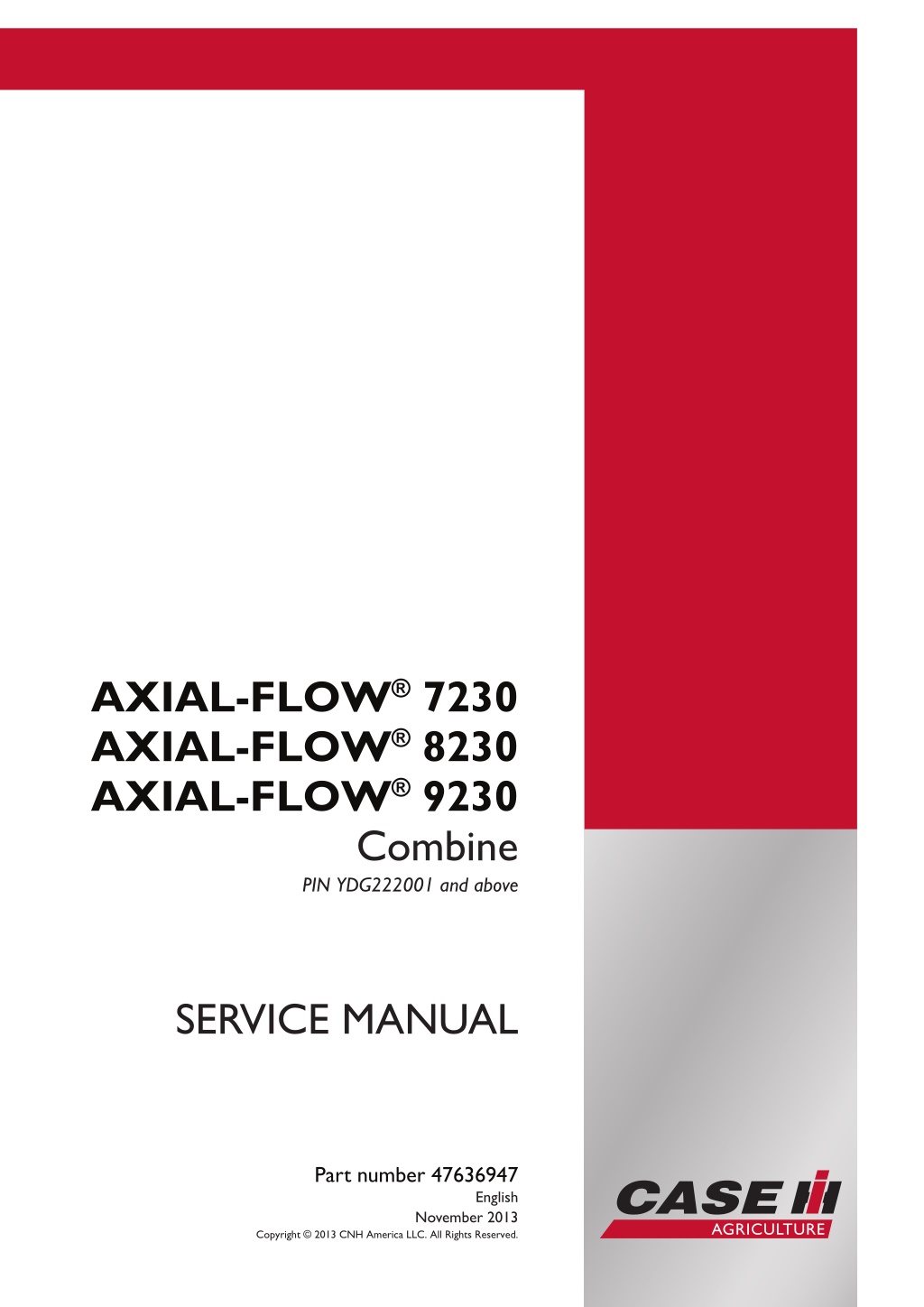
AXIAL-FLOW 7230 AXIAL-FLOW 8230 AXIAL-FLOW 9230 Combine PIN YDG222001 and above SERVICE MANUAL Part number 47636947 English November 2013 Copyright 2013 CNH America LLC. All Rights Reserved.
SERVICE MANUAL AXIAL-FLOW 7230 [YDG222001 - ] AXIAL-FLOW 8230 [YDG222001 - ] AXIAL-FLOW 9230 [YDG222001 - ] 47636947 15/11/2013 EN
Contents INTRODUCTION Engine....................................................................................... 10 [10.001] Engine and crankcase ............................................................. 10.1 [10.202] Air cleaners and lines .............................................................. 10.2 [10.210] Lift pump and lines ................................................................. 10.3 [10.216] Fuel tanks .......................................................................... 10.4 [10.218] Fuel injection system............................................................... 10.5 [10.310] Aftercooler.......................................................................... 10.6 [10.400] Engine cooling system ............................................................. 10.7 [10.414] Fan and drive ...................................................................... 10.8 [10.418] Rotary screen ...................................................................... 10.9 [10.450] Engine air compressor ........................................................... 10.10 [10.500] Selective Catalytic Reduction (SCR) exhaust treatment......................... 10.11 Main gearbox and drive............................................................... 14 [14.100] Main gearbox and drive ............................................................ 14.1 Transmission.............................................................................. 21 [21.100] Mechanical transmission lubrication system ....................................... 21.1 [21.114] Mechanical transmission ........................................................... 21.2 [21.130] Mechanical transmission external controls......................................... 21.3 [21.145] Gearbox internal components...................................................... 21.4 [21.182] Differential.......................................................................... 21.5 Front axle system ....................................................................... 25 [25.100] Powered front axle ................................................................. 25.1 [25.108] Final drive hub, steering knuckles, and shafts ..................................... 25.2 [25.310] Final drives......................................................................... 25.3 Rear axle system........................................................................ 27 47636947 15/11/2013
https://www.ebooklibonline.com Hello dear friend! Thank you very much for reading. Enter the link into your browser. The full manual is available for immediate download. https://www.ebooklibonline.com
[27.100] Powered rear axle.................................................................. 27.1 [27.124] Final drive hub, steering knuckles, and shafts ..................................... 27.2 Hydrostatic drive......................................................................... 29 [29.100] Transmission and steering hydrostatic control..................................... 29.1 [29.202] Hydrostatic transmission ........................................................... 29.2 [29.218] Pump and motor components...................................................... 29.3 [29.300] Rear hydrostatic transmission...................................................... 29.4 Power Take-Off (PTO)................................................................. 31 [31.146] Front Power Take-Off (PTO) ....................................................... 31.1 Brakes and controls .................................................................... 33 [33.110] Parking brake or parking lock ...................................................... 33.1 [33.202] Hydraulic service brakes ........................................................... 33.2 Hydraulic systems....................................................................... 35 [35.000] Hydraulic systems.................................................................. 35.1 [35.102] Pump control valves................................................................ 35.2 [35.106] Variable displacement pump ....................................................... 35.3 [35.220] Auxiliary hydraulic pump and lines................................................. 35.4 [35.300] Reservoir, cooler, and filters........................................................ 35.5 [35.350] Safety and main relief valves ...................................................... 35.6 [35.359] Main control valve.................................................................. 35.7 [35.410] Header or attachment height system .............................................. 35.8 [35.415] Header or attachment tilting system ............................................... 35.9 [35.440] Grain tank unload system........................................................ 35.10 [35.536] Crop processor system .......................................................... 35.11 Steering..................................................................................... 41 [41.101] Steering control .................................................................... 41.1 [41.200] Hydraulic control components...................................................... 41.2 [41.216] Cylinders ........................................................................... 41.3 47636947 15/11/2013
[41.432] Autoguidance steering ............................................................. 41.4 Wheels...................................................................................... 44 [44.511] Front wheels........................................................................ 44.1 [44.520] Rear wheels........................................................................ 44.2 Tracks and track suspension........................................................ 48 [48.100] Tracks .............................................................................. 48.1 [48.130] Track frame and driving wheels.................................................... 48.2 [48.134] Track tension units ................................................................. 48.3 [48.138] Track rollers ........................................................................ 48.4 Cab climate control..................................................................... 50 [50.100] Heating............................................................................. 50.1 [50.200] Air conditioning..................................................................... 50.2 Electrical systems....................................................................... 55 [55.000] Electrical system ................................................................... 55.1 [55.010] Fuel injection system............................................................... 55.2 [55.011] Fuel tank system ................................................................... 55.3 [55.012] Engine cooling system ............................................................. 55.4 [55.013] Engine oil system .................................................................. 55.5 [55.014] Engine intake and exhaust system................................................. 55.6 [55.015] Engine control system.............................................................. 55.7 [55.050] Heating, Ventilation, and Air-Conditioning (HVAC) control system................. 55.8 [55.100] Harnesses and connectors......................................................... 55.9 [55.201] Engine starting system........................................................... 55.10 [55.202] Cold start aid ..................................................................... 55.11 [55.301] Alternator......................................................................... 55.12 [55.302] Battery............................................................................ 55.13 [55.408] Warning indicators, alarms, and instruments .................................... 55.14 [55.421] Feeding control system .......................................................... 55.15 [55.426] Harvest material flow control system............................................. 55.16 47636947 15/11/2013
[55.628] Threshing electrical control ...................................................... 55.17 [55.640] Electronic modules............................................................... 55.18 [55.836] Rotary separator control ......................................................... 55.19 [55.988] Selective Catalytic Reduction (SCR) electrical system .......................... 55.20 [55.DTC] FAULT CODES.................................................................. 55.21 Attachments/Headers.................................................................. 58 [58.130] Attachment/Header frame.......................................................... 58.1 Product feeding.......................................................................... 60 [60.105] Floating roll, feed chain, and drive ................................................. 60.1 [60.110] Feeder housing..................................................................... 60.2 [60.112] Stone trapping system ............................................................. 60.3 [60.150] Feeder drive system ............................................................... 60.4 Threshing .................................................................................. 66 [66.000] Threshing .......................................................................... 66.1 [66.110] Concave control system............................................................ 66.2 [66.260] Threshing mechanism drive system ............................................... 66.3 [66.331] Rotor ............................................................................... 66.4 Separation................................................................................. 72 [72.220] Discharge beater................................................................... 72.1 [72.420] Rotary separator ................................................................... 72.2 Residue handling........................................................................ 73 [73.210] Straw chopper drive system........................................................ 73.1 [73.215] Straw chopper electro-magnetic clutch support.................................... 73.2 [73.230] Straw chopper...................................................................... 73.3 [73.AAA] Residue handling generic sub-group.............................................. 73.4 Cleaning.................................................................................... 74 [74.000] Cleaning............................................................................ 74.1 [74.100] Self-leveling frame ................................................................. 74.2 47636947 15/11/2013
[74.101] Cleaning drive systems ............................................................ 74.3 [74.110] Grain pan........................................................................... 74.4 [74.114] Upper shaker shoe ................................................................. 74.5 [74.118] Lower shaker shoe ................................................................. 74.6 [74.130] Fan housing........................................................................ 74.7 [74.136] Fan drive system................................................................... 74.8 [74.140] Tailings return system.............................................................. 74.9 Crop storage / Unloading............................................................. 80 [80.101] Clean grain elevator................................................................ 80.1 [80.150] Grain tank .......................................................................... 80.2 [80.175] Grain tank unload drive system .................................................... 80.3 [80.180] Grain tank unload .................................................................. 80.4 Platform, cab, bodywork, and decals............................................. 90 [90.100] Engine hood and panels ........................................................... 90.1 [90.105] Machine shields and guards ....................................................... 90.2 [90.124] Pneumatically-adjusted operator seat.............................................. 90.3 [90.150] Cab................................................................................. 90.4 [90.151] Cab interior......................................................................... 90.5 47636947 15/11/2013
INTRODUCTION 47636947 15/11/2013 1
INTRODUCTION Safety rules Signal word definitions AXIAL-FLOW 7230 WE, AXIAL-FLOW 8230 WE, AXIAL-FLOW 9230 WE Personal safety This is the safety alert symbol. It is used to alert you to potential personal injury hazards. Obey all safety messages that follow this symbol to avoid possible death or injury. Throughout this manual you will find the signal words DANGER, WARNING, and CAUTION followed by special in- structions. These precautions are intended for the personal safety of you and those working with you. Read and understand all the safety messages in this manual before you operate or service the machine. DANGER indicates a hazardous situation that, if not avoided, will result in death or serious injury. WARNING indicates a hazardous situation that, if not avoided, could result in death or serious injury. CAUTION indicates a hazardous situation that, if not avoided, could result in minor or moderate injury. FAILURE TO FOLLOW DANGER, WARNING, AND CAUTION MESSAGES COULD RESULT IN DEATH OR SERIOUS INJURY. Machine safety NOTICE: Notice indicates a situation that, if not avoided, could result in machine or property damage. Throughout this manual you will find the signal word Notice followed by special instructions to prevent machine or property damage. The word Notice is used to address practices not related to personal safety. Information NOTE: Note indicates additional information that clarifies steps, procedures, or other information in this manual. Throughout this manual you will find the word Note followed by additional information about a step, procedure, or other information in the manual. The word Note is not intended to address personal safety or property damage. 47636947 15/11/2013 4
INTRODUCTION Personal safety AXIAL-FLOW 7230, AXIAL-FLOW 7230 WE, AXIAL-FLOW 8230, AXIAL-FLOW 8230 WE, AXIAL-FLOW 9230, AXIAL-FLOW 9230 WE, AXIAL-FLOW 30 Series WARNING Risk of harm during maintenance of the machine! Before you start servicing the machine, attach a DO NOT OPERATE warning tag to the machine in a visible area. Failure to comply could result in death or serious injury. W1242A Attach a DO NOT OPERATE (TAG) to the machine in an area that is clearly visible whenever the machine is not operating properly and/or requires service. Complete the tag information for the "REASON" the tag is attached by describing the malfunction or service required. Validate the reason for attaching the tag by signing your name in the designated area on the tag. The tag should only be removed by the person who signed and attached the tag, after validating the repairs or services have been completed. 47636947 15/11/2013 5
INTRODUCTION Safety rules - Ecology and the environment AXIAL-FLOW 7230 WE, AXIAL-FLOW 8230 WE, AXIAL-FLOW 9230 WE Soil, air, and water are vital factors of agriculture and life in general. When legislation does not yet rule the treatment of some of the substances required by advanced technology, sound judgment should govern the use and disposal of products of a chemical and petrochemical nature. NOTE: The following are recommendations that may be of assistance: Become acquainted with and ensure that you understand the relative legislation applicable to your country. Where no legislation exists, obtain information from suppliers of oils, filters, batteries, fuels, antifreeze, cleaning agents, etc., with regard to their effect on man and nature and how to safely store, use, and dispose of these substances. Agricultural consultants will, in many cases, be able to help you as well. Helpful hints Avoid filling tanks using cans or inappropriate pressurized fuel delivery systems that may cause considerable spillage. In general, avoid skin contact with all fuels, oils, acids, solvents, etc. Most of them contain substances that may be harmful to your health. Modern oils contain additives. Do not burn contaminated fuels and or waste oils in ordinary heating systems. Avoid spillage when draining off used engine coolant mixtures, engine, gearbox and hydraulic oils, brake fluids, etc. Do not mix drained brake fluids or fuels with lubricants. Store them safely until they can be disposed of in a proper way to comply with local legislation and available resources. Modern coolant mixtures, i.e. antifreeze and other additives, should be replaced every two years. They should not be allowed to get into the soil, but should be collected and disposed of properly. Do not open the air-conditioning system yourself. It contains gases that should not be released into the atmosphere. Your CASE IH dealer or air conditioning specialist has a special extractor for this purpose and will have to recharge the system properly. Repair any leaks or defects in the engine cooling or hydraulic system immediately. Do not increase the pressure in a pressurized circuit as this may lead to a component failure. Protect hoses during welding as penetrating weld splatter may burn a hole or weaken them, allowing the loss of oils, coolant, etc. 47636947 15/11/2013 6
SERVICE MANUAL Engine AXIAL-FLOW 7230 [YDG222001 - ] AXIAL-FLOW 8230 [YDG222001 - ] AXIAL-FLOW 9230 [YDG222001 - ] 47636947 15/11/2013 10
Engine - Engine and crankcase Engine - Remove AXIAL-FLOW 7230 WARNING Avoid injury! Always do the following before lubricating, maintaining, or servicing the machine. 1. Disengage all drives. 2. Engage parking brake. 3. Lower all attachments to the ground, or raise and engage all safety locks. 4. Shut off engine. 5. Remove key from key switch. 6. Switch off battery key, if installed. 7. Wait for all machine movement to stop. Failure to comply could result in death or serious injury. W0047A WARNING Heavy objects! Lift and handle all heavy components using lifting equipment with adequate capacity. Always support units or parts with suitable slings or hooks. Make sure the work area is clear of all bystanders. Failure to comply could result in death or serious injury. W0398A Prior operation: Engine cooling system - Drain fluid (10.400) Prior operation: Deaeration tank - Remove (10.400) Prior operation: Engine hood - Remove (90.105) Prior operation: Radiator hoses - Remove (10.400) Prior operation: Air intake system - Remove (10.202) Prior operation: Fan and drive - Remove (10.414) Prior operation: Air conditioning - Service instruction (50.200) Prior operation: Fuel supply lines Low pressure - Remove (10.210) Prior operation: Aftercooler - Remove (10.310) Prior operation: Rotary screen drive belt or chain - Remove (10.418) Prior operation: Selective Catalytic Reduction (SCR) exhaust treatment - Remove (10.500) Prior operation: Diesel Exhaust Fluid (DEF)/AdBlue lines - Remove (10.500) Prior operation: Diesel Exhaust Fluid (DEF)/AdBlue delivery line to dosing injector - Remove (10.500) Prior operation: Selective Catalytic Reduction (SCR) muffler and catalyst - Remove (10.500) Prior operation: Central wire harness - Remove (55.100) 47636947 15/11/2013 10.1 [10.001] / 4
Engine - Engine and crankcase 1. Attach a suitable chain to the front lift eye (1) at the front of the engine. 1 86070259 2. Attach a suitable chain to the back lift eye (1) at the rear of the engine. 2 86070260 3. Connect the lift chain to a suitable lifting device. 4. Raise the lifting device enough to support the engine during removal of the engine mounting bolts. NOTE: Illustration is for reference only. It may not be the actual engine. NOTE: The lifting device should be rated for at least 907.2 kg (2000 lb). Allow enough clearance to lift the engine from the combine, approximately 7.0 m (23 ft) from the floor. 3 10013136 47636947 15/11/2013 10.1 [10.001] / 5
Engine - Engine and crankcase 5. From the grain tank side of the engine, loosen the front, enginemountingbolts(1). Donotremovethemounting bolts at this time. 6. From the platform side, loosen the front, engine mount- ing bolts (2). Do not remove the mounting bolts at this time. 4 NHIL13AF01521AA 7. From the rear of the engine, loosen but do not remove all the bolts and washers (1) that couple the engine to the gearbox. There are twelve bolts and washers in total. 8. For safety reasons to the radiators, place a sheet of plywood, cut to size, in front of the cooler box for pro- tection. 9. With the engine securely supported by the lifting de- vice, remove all of the engine mounting bolts and the engine to the gearbox coupling bolts that were loos- ened in the previous steps. 10. Slide the engine towards the cooler box to disengage the flex plate from the gearbox input shaft. 11. Carefully lift the engine from the frame and remove from the combine. 5 NHIL13AF01522AA Next operation: Engine - Install (10.001). 47636947 15/11/2013 10.1 [10.001] / 6
Engine - Engine and crankcase Engine - Install AXIAL-FLOW 7230 WE WARNING Avoid injury! Always do the following before lubricating, maintaining, or servicing the machine. 1. Disengage all drives. 2. Engage parking brake. 3. Lower all attachments to the ground, or raise and engage all safety locks. 4. Shut off engine. 5. Remove key from key switch. 6. Switch off battery key, if installed. 7. Wait for all machine movement to stop. Failure to comply could result in death or serious injury. W0047A WARNING Heavy objects! Lift and handle all heavy components using lifting equipment with adequate capacity. Always support units or parts with suitable slings or hooks. Make sure the work area is clear of all bystanders. Failure to comply could result in death or serious injury. W0398A Prior operation: Engine - Remove (10.001) 1. Before installing the engine, apply LOCTITE SILVER GRADE ANTI-SEIZE 767 to the input shaft (1) of the gear- box. 1 83070284 2. Attach a suitable chain to the front lift eye (1) at the front of the engine. 2 86070259 47636947 15/11/2013 10.1 [10.001] / 7
Engine - Engine and crankcase 3. Attach a suitable chain to the back lift eye (1) at the rear of the engine. 3 86070260 4. Connect the lift chain to a suitable lifting device. 5. Carefully lift the engine above the combine and lower into position in the frame. NOTE: Illustration is for reference only. It may not be the actual engine. NOTE: The lifting device should be rated for at least 907.2 kg (2000 lb). Allow enough clearance to lift the en- gine from the combine, approximately 907.2 kg (2000 lb) from the floor. 4 10013136 6. For safety reasons to the radiator, place a sheet of ply- wood, cut to size, in front of the radiator for protection. 7. Slide the engine towards the gearbox onto the gear box input shaft. 8. Align the holes of the gearbox with the engine and hand start a bolt with a washer (1) on each side of the cou- pling, going back and forth until all bolts with a washers are installed. 5 NHIL13AF01522AA 47636947 15/11/2013 10.1 [10.001] / 8
Engine - Engine and crankcase 9. With the engine positioned in the frame, align the front mounting hole on the grain tank side and install the bolt with washers (1) into the mount. Do not tighten yet. 10. Align the front mounting hole on the platform side. In- stall the bolt with washers (1) into the mount. 11. Tighten and torque the front engine mounting bolts to 217 Nm (160.1 lb ft). 12. Tighten and torque the engine gearbox bolts to 41 - 51 Nm (30.2 - 37.6 lb ft). 6 NHIL13AF01521AA 47636947 15/11/2013 10.1 [10.001] / 9
Engine - Engine and crankcase Next Operations Central wire harness - Install (55.100) Selective Catalytic Reduction (SCR) muffler and catalyst - Install (10.500) Diesel Exhaust Fluid (DEF)/AdBlue lines - Install (10.500) Selective Catalytic Reduction (SCR) exhaust treatment - Install (10.500) Diesel Exhaust Fluid (DEF)/AdBlue delivery line to dosing injector - Install (10.500) Rotary screen drive belt or chain - Install (10.418) Aftercooler - Install (10.310) Fuel supply lines Low pressure - Install (10.210) Air conditioning - Service instruction (50.200) Fan and drive - Install (10.414) Air intake system - Install (10.202) Radiator hoses - Install (10.400) Engine hood and panels - Install (90.100) Deaeration tank - Install (10.400) Engine cooling system - Filling (10.400) 13. Connect the battery cables to the batteries (1) if they were removed or engage the battery connect switch (2). 7 NHIL13AF01523BB 8 NHIL13AF00586AA 47636947 15/11/2013 10.1 [10.001] / 10
Engine - Engine and crankcase 14. Disconnectthefuelpumpwireconnector(1)todisable the fuel pump (2). 15. Check the engine oil level and top off if necessary. 16. Crank the engine over for three ten second intervals. This will distribute lubricating oil to the engine oper- ating systems and will allow oil pressure to be built before starting the engine. 9 NHIL13AF00582AA 17. Connect the fuel pump wire connector (1) to the fuel pump (2) and bleed the air from fuel injection system, as described in the Operators manual. 18. Start the engine and check all hoses, fittings and clamps for leaks. NOTICE: Monitor the instrument warning light bar at all times during initial engine start up to ensure the engine has proper oil pressure. Shut down the engine immediately if oil pressure is not adequate. 19. Ensureallelectricalcomponentsareworkingproperly. 10 NHIL13AF00582AA 47636947 15/11/2013 10.1 [10.001] / 11
Engine - Engine and crankcase Engine - Remove AXIAL-FLOW 8230, AXIAL-FLOW 9230 WARNING Avoid injury! Always do the following before lubricating, maintaining, or servicing the machine. 1. Disengage all drives. 2. Engage parking brake. 3. Lower all attachments to the ground, or raise and engage all safety locks. 4. Shut off engine. 5. Remove key from key switch. 6. Switch off battery key, if installed. 7. Wait for all machine movement to stop. Failure to comply could result in death or serious injury. W0047A WARNING Heavy objects! Lift and handle all heavy components using lifting equipment with adequate capacity. Always support units or parts with suitable slings or hooks. Make sure the work area is clear of all bystanders. Failure to comply could result in death or serious injury. W0398A Prior operation: Engine cooling system - Drain fluid (10.400) Prior operation: Deaeration tank - Remove (10.400) Prior operation: Engine hood - Remove (90.105) Prior operation: Radiator hoses - Remove (10.400) Prior operation: Air intake system - Remove (10.202) Prior operation: Fan and drive - Remove (10.414) Prior operation: Air conditioning - Service instruction (50.200) Prior operation: Fuel supply lines Low pressure - Remove (10.210) Prior operation: Aftercooler - Remove (10.310) Prior operation: Rotary screen drive belt or chain - Remove (10.418) Prior operation: Selective Catalytic Reduction (SCR) exhaust treatment - Remove (10.500) Prior operation: Diesel Exhaust Fluid (DEF)/AdBlue lines - Remove (10.500) Prior operation: Diesel Exhaust Fluid (DEF)/AdBlue delivery line to dosing injector - Remove (10.500) Prior operation: Selective Catalytic Reduction (SCR) muffler and catalyst - Remove (10.500) Prior operation: Central wire harness - Remove (55.100) 47636947 15/11/2013 10.1 [10.001] / 12
Engine - Engine and crankcase 1. Attach a suitable chain to the front lift eye (1) at the front of the engine. 1 86070259 2. Attach a suitable chain to the back lift eye (1) at the rear of the engine. 2 86070260 3. Connect the lift chain to a suitable lifting device. 4. Raise the lifting device enough to support the engine during removal of the engine mounting bolts. NOTE: Illustration is for reference only. It may not be the actual engine. NOTE: The lifting device should be rated for at least 907.2 kg (2000 lb). Allow enough clearance to lift the engine from the combine, approximately 7.0 m (23 ft) from the floor. 3 10013136 47636947 15/11/2013 10.1 [10.001] / 13
Suggest: If the above button click is invalid. Please download this document first, and then click the above link to download the complete manual. Thank you so much for reading
Engine - Engine and crankcase 5. From the grain tank side of engine, loosen the front two enginemountingbolts(1). Donotremovethemounting bolts at this time. 6. From the platform side, loosen the two front, engine mounting bolts (2). Do not remove the mounting bolts at this time. 4 NHIL13AF01524AA 7. Loosen but do not remove all the bolts and washers (1) that couple the engine to the gearbox. There are twelve bolts and washers in total. 8. For safety reasons to the radiators, place a sheet of plywood, cut to size, in front of the cooler box for pro- tection. 9. With the engine securely supported by the lifting de- vice, remove all of the engine mounting bolts and the engine to the gearbox coupling bolts that were loos- ened in the previous steps. 10. Slide the engine towards the cooler box to disengage the flex plate from the gearbox input shaft. 5 83090610 11. Carefully lift the engine from the frame and remove from the combine. Next operation: Engine - Install (10.001). 47636947 15/11/2013 10.1 [10.001] / 14
https://www.ebooklibonline.com Hello dear friend! Thank you very much for reading. Enter the link into your browser. The full manual is available for immediate download. https://www.ebooklibonline.com