Simulation of Turbulent Pipe Flow Analysis in Fluid Mechanics Lab

This content describes a lab session in Mechanics of Fluids and Transport Processes, focusing on simulating turbulent pipe flow using Computational Fluid Dynamics (CFD). It covers topics such as Reynolds number, turbulent flow features, turbulent models, and the simulation procedure. Students will analyze axial velocity profiles, pressure, and wall shear stress, comparing CFD results with experimental data to understand laminar vs. turbulent flow concepts.

Download Presentation

Please find below an Image/Link to download the presentation.
The content on the website is provided AS IS for your information and personal use only. It may not be sold, licensed, or shared on other websites without obtaining consent from the author. Download presentation by click this link. If you encounter any issues during the download, it is possible that the publisher has removed the file from their server.
E N D
Presentation Transcript
1. Overview of Pipe Flow 2. CFD Process 3. Geometry 4. Mesh 5. Physics 6. Results 9/11/2024 2 ENGR:2510 Mechanics of Fluids and Transport Processes 2016F
Simulation of turbulent pipe flow will be conducted for this lab Axial velocity profile, centerline velocity, centerline pressure, and wall shear stress will be analyzed Computational fluid dynamics (CFD) results for friction factor and velocity profile and centerline pressure will be compared to experimental fluid dynamics (EFD) This lab will cover concept of laminar vs. turbulent flow and developing length for pipe flows 9/11/2024 3 ENGR:2510 Mechanics of Fluids and Transport Processes 2016F
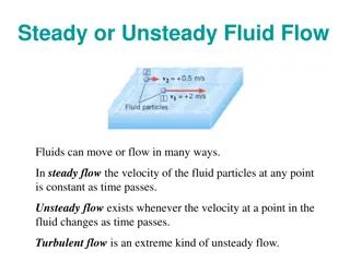
Flow in pipe with Reynolds number (Re) ?? =?? where U is an inflow velocity, D is a diameter of pipe, ? is a kinematic viscosity Laminar : Re < 2300 Turbulent : Re > 2300 ?=???????? ?????? ??????? ?????? Turbulent flow features Irregularity Diffusivity Dissipation Energy cascade Analysis of turbulent flow Mean value in time vs. space Turbulent model Reynolds stress model (in RANS) k-epsilon model Flow visualization of transition from laminar to turbulent flow Turbulent mixing flow in pipe 9/11/2024 4 ENGR:2510 Mechanics of Fluids and Transport Processes 2016F
The overall procedure for simulation of pipe flow is shown on chart below Although we will be making the mesh before we define the physics you have to know the physics to design appropriate mesh. Physics Geometry Results Solution Mesh Structure (ANSYS Mesh) Pipe (ANSYS Design Modeler) General (ANSYS Fluent - Setup) Solution Methods (ANSYS Fluent - Solution) Monitors (ANSYS Fluent - Solution) Plots (ANSYS Fluent- Results) Model (ANSYS Fluent - Setup) Non-uniform (ANSYS Mesh) Graphics and Animations (ANSYS Fluent- Results) Boundary Conditions (ANSYS Fluent -Setup) Turbulent Reference Values (ANSYS Fluent - Setup) Solution Initialization (ANSYS Fluent -Solution) 9/11/2024 5 ENGR:2510 Mechanics of Fluids and Transport Processes 2016F
Symmetric property of the flow is used to create 2D representation of the 3D pipe flow R D Parameter Radius of pipe, R Diameter of pipe, D Length of pipe, L Value L 0.02619 m 0.05238 m 6.096 m Wall Flow Inlet Outlet =location of the EFD pressure tab #4, and will be treated as an outlet in CFD Center 9/11/2024 6 ENGR:2510 Mechanics of Fluids and Transport Processes 2016F
Previously, in Pre-lab1, uniform grid distribution was used for laminar flow Velocity profile of turbulent flow need more resolution near the wall because of its larger velocity gradient (? ?? ?/? ?? ?) near the wall than in laminar flow Non-uniform mesh is better for the turbulent flow Laminar Turbulent 9/11/2024 7 ENGR:2510 Mechanics of Fluids and Transport Processes 2016F
Turbulent flow Air properties (Need to be extracted from the EFD) Boundary Conditions (BC) (Need to be extracted from the EFD) No-slip: velocities and pressure gradient is zero (??= 0,??= 0, Symmetric: radial velocity and gradients of axial velocity and pressure are zero (??? ?? ??= 0) ??= 0, ??= 0, ?? ??= 0) ??= 0) Inlet velocity: uniform constant velocity (??= ???? ??? ????? ???????? [?/?],??= 0,?? Outlet: (gauge) pressure is imposed to the boundary (??? ??= 0, ??? ??= 0,? =??????=EFD tab 4 pressure) r Wall No slip BC Inlet Velocity inlet BC Flow Outlet Pressure outlet BC x Center Axisymmetric BC Zero slop at center or ??? ??= 0 CFD Input tab in EFD Lab 2 Data Reduction Sheet 9/11/2024 8 ENGR:2510 Mechanics of Fluids and Transport Processes 2016F
Validation of the wall friction factor FactorCFD 0.01745 FactorEFD 0.01801 %Error 3.07 Validation of the velocity profile at the developed region and the pressure distribution 9/11/2024 9 ENGR:2510 Mechanics of Fluids and Transport Processes 2016F
Laminar Turbulent Developing region Developed region Developing region Developed region 9/11/2024 10 ENGR:2510 Mechanics of Fluids and Transport Processes 2016F
Deadline for the CFD Lab 1 report is two weeks after from your CFD lab 1 (Today) Please download the CFD Lab1 Report Template.doc under the CFD Lab 1 section in the website, and fill out both Pre-lab1 and Lab1 answers (there s no separate report for the Pre-lab 1) Pre-lab 1 questions will be graded separately, so it doesn t need to be attached to the report Use the Lab drop-box when turning in your lab reports Come to the office hours for any help 9/11/2024 11 ENGR:2510 Mechanics of Fluids and Transport Processes 2016F


")