Steel Design for Combined Forces: AISC Chapter H Summary and Equations

Steel design for members subject to axial force and flexure, addressing doubly and singly symmetric members, interaction of flexure and compression, required axial compressive and flexural strength calculations based on LRFD load combinations. Equations provided for design considerations in AISC Specification Chapter H.

Download Presentation

Please find below an Image/Link to download the presentation.
The content on the website is provided AS IS for your information and personal use only. It may not be sold, licensed, or shared on other websites without obtaining consent from the author. Download presentation by click this link. If you encounter any issues during the download, it is possible that the publisher has removed the file from their server.
E N D
Presentation Transcript
DESIGN OF MEMBERS FOR COMBINED FORCES CE 470: Steel Design By: Amit H. Varma
Design of Members for Combined Forces Chapter H of the AISC Specification This chapter addresses members subject to axial force and flexure about one or both axes. H1 - Doubly and singly symmetric members H1.1 Subject to flexure and compression The interaction of flexure and compression in doubly symmetric members and singly symmetric members for which 0.1 Iyc/ Iy 0.9, that are constrained to bend about a geometric axis (x and/or y) shall be limited by the Equations shown below. Iycis the moment of inertia about the y-axis referred to the compression flange.
Design of Members for Combined Forces ForPr 0.2 Pc 1.0 +Mry Mcy Pr Pc +8 Mrx Mcx 9 ForPr 0.2 Pc 1.0 +Mry Mcy Pr 2Pc Mrx Mcx + where, x = subscript relating symbol to strong axis bending y = subscript relating symbol to weak axis bending
Design of Members for Combined Forces Pr= required axial compressive strength using LRFD load combinations Mr= required flexural strength using LRFD load combinations Pc= cPn= design axial compressive strength according to Chapter E Mc= bMn= design flexural strength according to Chapter F. c= 0.90 and b= 0.90
Design of Members for Combined Forces H1.2 Doubly and singly symmetric members in flexure and tension Use the same equations indicated earlier But, Pr= required tensile strength Pc= tPn= design tensile strength according to Chapter D, Section D2. t= 0.9 For doubly symmetric members, Cbin Chapter F may be multiplied by 1 +??? ???for axial tension that acts concurrently with flexure ?2??? ?? ; =1(LRFD) Where, ???= 2
Design of Members for Combined Forces H1.3 Doubly symmetric rolled compact members in single axis flexure and compression For doubly symmetric rolled compact members with ??? ???in flexure and compression with moments primarily about major axis, it is permissible to consider two independent limit states separately, namely, (i) in-plane instability, and (ii) out-of-plane or lateral-torsional buckling. This is instead of the combined approach of Section H1.1 ??? For members with followed. ??? 0.05, Section H1.1 shall be
Design of Members for Combined Forces For the limit state of in-plane instability, Equations H1-1 shall be used with Pc, Mrx, and Mcx determined in the plane of bending. For the limit state of out-of-plane/lateral torsional buckling: ?? ??? ??? 2 1.5 0.5?? ??? ????? + 1.0 where: ???= available compressive strength out of plane of bending ??= lateral torsional buckling modification factor (Section F1) ???=available lateral-torsional strength for strong axis flexure (Chapter F, using ??=1)
Design of Members for Combined Forces. The provisions of Section H1 apply to rolled wide-flange shapes, channels, tee-shapes, round, square, and rectangular tubes, and many other possible combinations of doubly or singly symmetric sections built-up from plates. cPY Section P-M interaction For zero-length beam-column cPY bMp
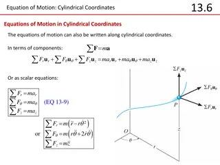
Design of Members for Combined Forces. P-M interaction curve according to Section H1.1 cPY P-M interaction for zero length Column axial load capacity accounting for x and y axis buckling cPn P-M interaction for full length cPn bMn bMp Beam moment capacity accounting for in-plane behavior and lateral-torsional buckling
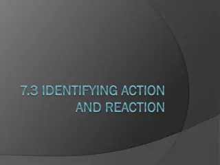
Design of Members for Combined Forces. P-M interaction according to Section H1.3 cPY P-M interaction for zero length Column axial load capacity accounting for x axis buckling Column axial load capacity accounting for y axis buckling cPnx P-M interaction In-plane, full length cPny P-M interaction Out-plane, full length cPnx bMn bMp Out-of-plane Beam moment capacity accounting for lateral-torsional buckling In-plane Beam moment capacity accounting for flange local buckling
Design of Members for Combined Forces. Steel Beam-Column Selection Tables Table 6-1 W shapes in Combined Axial and Bending 1 1 = n c P ( ) p kips 8 M = 1 ( ) b kip ft x 9 b nx 8 M = 1 ( ) b kip ft y 9 b ny + + 0 . 1 2 . 0 : If pP pP b M b M r r x rx y ry ( ) 9 pP + + 0 . 1 2 . 0 : r If pP b M b M r x rx y ry 2 8 The values of p and bx for each rolled W section is provided in Table 6-1 for different unsupported lengths KLy or Lb. The Table also includes the values of by, ty, and tr for all the rolled sections. These values are independent of length
Design of Members for Combined Forces. Table 6-1 is normally used with iteration to determine an appropriate shape. After selecting a trial shape, the sum of the load ratios reveals if that trial shape is close, conservative, or unconservative with respect to 1.0. When the trial shape is unconservative, and axial load effects dominate, the second trial shape should be one with a larger value of p. Similarly, when the X-X or Y-Y axis flexural effects dominate, the second trial shape should one with a larger value of bx or by, respectively. This process should be repeated until an acceptable shape is determined.
Estimating Required Forces - Analysis The beam-column interaction equation include both the required axial forces and moments, and the available capacities. The available capacities are based on column and beam strengths, and the P-M interaction equations try to account for their interactions. However, the required Pr and Mr forces are determined from analysis of the structure. This poses a problem, because the analysis SHOULD account for second-order effects. 1st order analysis DOES NOT account for second-order effects. What is 1st order analysis and what are second-order effects?
First-Order Analysis The most important assumption in 1st order analysis is that FORCE EQUILIBRIUM is established in the UNDEFORMED state. All the analysis techniques taught in CE270, CE371, and CE474 are first-order. These analysis techniques assume that the deformation of the member has NO INFLUENCE on the internal forces (P, V, M etc.) calculated by the analysis. This is a significant assumption that DOES NOT work when the applied axial forces are HIGH.
First-Order Analysis Results from a 1st order analysis M1 M2 P P V1 -V1 M(x) Free Body diagram In undeformed state x M(x) = M1+V1 x M2 M1 Moment diagram Has no influence of deformations or axial forces
Second Order Effects M1 M2 P P V1 -V1 M1 P M(x) In deformed state v(x) is the vertical deformation Free Body diagram V1 x M(x) = M1+V1 x + P v(x) M2 M1 Moment diagram Includes effects of deformations & axial forces
Second Order Effects Clearly, there is a moment amplification due to second- order effects. This amplification should be accounted for in the results of the analysis. The design moments for a braced frame (or frame restrained for sway) can be obtained from a first order analysis. But, the first order moments will have to amplified to account for second-order effects. According to the AISC specification, this amplification can be achieved with the factor B1 = B C 0 . 1 m 1 P 1 r P 1 e
Second Order Effects Pe1 = 2EI/(K1L)2 I =moment of inertia in the plane of bending K1=1.0 for braced case
Second Order Effects Sign Convention for M1/M2
Further Moment Amplification This second-order effect accounts for the deflection of the beam in between the two supported ends (that do not translate). That is, the second-order effects due to the deflection from the chord of the beam. When the frame is free to sway, then there are additional second-order effects due to the deflection of the chord. The second-order effects associated with the sway of the member ( ) chord.
Further Moment Amplification P Mo Mmax P Mo + = Mo Mo P As you can see, there is a moment amplification due to the sway of the beam chord by . This is also referred as the story P- effect that produces second-order moments in sway frames due to inter-story drift. All the beam-columns in the story will have P- effect
Further Moment Amplification The design moments for a sway frame (or unrestrained frame) can be obtained from a first order analysis. But, the first order moments will have to amplified to account for second-order P- effects. According to the AISC specification, this amplification can be achieved with the factor B2 1 2 P = 0 . 1 B story P 1 e story
The final understanding The required forces (Pr, Vr, and Mr) can be obtained from a first-order analysis of the frame structure. But, they have to be amplified to account for second-order effects. For the braced frame, only the P- effects of deflection from the chord will be present. For the sway frame, both the P- and the P- effects of deflection from and of the chord will be present. These second-order effects can be accounted for by the following approach. Step 1 - Develop a model of the building structure, where the sway or interstory drift is restrained at each story. Achieve this by providing a horizontal reaction at each story Step 2 - Apply all the factored loads (D, L, W, etc.) acting on the building structure to this restrained model.
The final understanding Step 3 - Analyze the restrained structure. The resulting forces are referred as Pnt, Vnt, Mnt, where nt stands for no translation (restrained). The horizontal reactions at each story have to be stored Step 4 - Go back to the original model, and remove the restraints at each story. Apply the horizontal reactions at each story with a negative sign as the new loading. DO NOT apply any of the factored loads. Step 5 - Analyze the unrestrained structure. The resulting forces are referred as Plt, Vlt, and Mlt, where lt stands for lateral translation (free). Step 6 - Calculate the required forces for design using Pr = Pnt + B2 Plt Vr = Vnt + B2 Vlt Mr = B1 Mnt + B2 Mlt