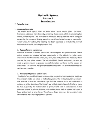
Caterpillar Cat 304.5 Mini Hydraulic Excavator (Prefix ANR) Service Repair Manual Instant Download
Please open the website below to get the complete manualnn//
Download Presentation

Please find below an Image/Link to download the presentation.
The content on the website is provided AS IS for your information and personal use only. It may not be sold, licensed, or shared on other websites without obtaining consent from the author. Download presentation by click this link. If you encounter any issues during the download, it is possible that the publisher has removed the file from their server.
E N D
Presentation Transcript
Service Repair Manual Models 304.5 M ini Hydraulic Excavator
304.5 Mini Hydraulic Excavator ANR00001-UP (MACHINE) POWERED BY 3024 E... 1/9 Shutdown SIS Previous Screen Product: MINI HYD EXCAVATOR Model: 304.5 MINI HYD EXCAVATOR ANR Configuration: 304.5 Mini Hydraulic Excavator ANR00001-UP (MACHINE) POWERED BY 3024 Engine Disassembly and Assembly 304.5 Mini Hydraulic Excavator Machine Systems Media Number -RENR3548-04 Publication Date -01/08/2008 Date Updated -18/08/2008 i01368358 Piston Pump - Disassemble SMCS - 5070-015 Disassembly Procedure Table 1 REQUIRED TOOLS Tool Part Number Part Description Qty A 1P-1857 Snap Ring Pliers 1 B 1P-1859 Snap Ring Pliers 1 Start By: A. Remove the piston pump. Refer to Disassembly and Assembly, "Piston Pump - Remove". NOTICE Care must be taken to ensure that fluids are contained during performance of inspection, maintenance, testing, adjusting and repair of the product. Be prepared to collect the fluid with suitable containers before opening any compartment or disassembling any component containing fluids. Refer to Special Publication, NENG2500, "Caterpillar Tools and Shop Products Guide" for tools and supplies suitable to collect and contain fluids on Caterpillar products. Dispose of all fluids according to local regulations and mandates. https://127.0.0.1/sisweb/sisweb/techdoc/techdoc_print_page.jsp?returnurl=/sis... 2020/2/21
304.5 Mini Hydraulic Excavator ANR00001-UP (MACHINE) POWERED BY 3024 E... 2/9 Note: Put identification marks on the pump and on all lines for installation purposes. Plug all lines. This will help to prevent fluid loss and this helps to keep contaminants from entering the system. Note: Cleanliness is an important factor. Before the disassembly procedure, the exterior of the component should be thoroughly cleaned. This will help to prevent dirt from entering the internal mechanism. Illustration 1 g00722015 1. Remove allen head screw (1) . 2. Remove hub (2) from the shaft. Illustration 2 g00721949 3. Remove collar (3) from the pump head. 4. Remove coupling (4) from the pump head. 5. Remove O-ring (5) from the pump head. Note: Do not remove large allen head screw on valve (7). https://127.0.0.1/sisweb/sisweb/techdoc/techdoc_print_page.jsp?returnurl=/sis... 2020/2/21
https://www.ebooklibonline.com Hello dear friend! Thank you very much for reading. Enter the link into your browser. The full manual is available for immediate download. https://www.ebooklibonline.com
304.5 Mini Hydraulic Excavator ANR00001-UP (MACHINE) POWERED BY 3024 E... 3/9 Illustration 3 g00722021 6. Remove two allen head screws (6) from the valve. 7. Remove valve (7) . Illustration 4 g00722028 Illustration 5 g00722037 https://127.0.0.1/sisweb/sisweb/techdoc/techdoc_print_page.jsp?returnurl=/sis... 2020/2/21
304.5 Mini Hydraulic Excavator ANR00001-UP (MACHINE) POWERED BY 3024 E... 4/9 8. Remove piston (8) from the pump head. 9. Remove O-ring (9) from piston (8) . Note: One allen head screw (10) is longer than the other three allen head screws. Illustration 6 g00722043 10. Remove four allen head screws (10) . 11. Remove pump head (11) from the pump body. Illustration 7 g00722051 12. Rotate the pump head to the other side. 13. Remove O-ring (12) from the pump head. 14. Remove four O-rings (13) from the pump head. 15. Remove plate (14) from the pump head. https://127.0.0.1/sisweb/sisweb/techdoc/techdoc_print_page.jsp?returnurl=/sis... 2020/2/21
304.5 Mini Hydraulic Excavator ANR00001-UP (MACHINE) POWERED BY 3024 E... 5/9 Illustration 8 g00722064 16. Remove two allen head screws (15) from the piston block. 17. Remove piston block (16) from the pump head. Illustration 9 g00722086 18. Remove O-rings (17), (18), and (19) from the piston block. Illustration 10 g00722089 https://127.0.0.1/sisweb/sisweb/techdoc/techdoc_print_page.jsp?returnurl=/sis... 2020/2/21
304.5 Mini Hydraulic Excavator ANR00001-UP (MACHINE) POWERED BY 3024 E... 6/9 19. Remove springs (20) and (21) from the pump body. 20. Use Tooling (A) to remove snap ring (22) . 21. Remove pump rotating group (23) from the shaft. Illustration 11 g00722106 22. Remove spring retainer (24) from the swashplate. Illustration 12 g00722113 23. Remove four allen head screws (25) from plate (26) . 24. Remove plate (26) from the pump body. https://127.0.0.1/sisweb/sisweb/techdoc/techdoc_print_page.jsp?returnurl=/sis... 2020/2/21
304.5 Mini Hydraulic Excavator ANR00001-UP (MACHINE) POWERED BY 3024 E... 7/9 Illustration 13 g00722120 25. Rotate plate (26) to the other side. 26. Remove O-ring (27) from the plate. Illustration 14 g00722384 27. Remove valve assembly (28) from the pump body. https://127.0.0.1/sisweb/sisweb/techdoc/techdoc_print_page.jsp?returnurl=/sis... 2020/2/21
304.5 Mini Hydraulic Excavator ANR00001-UP (MACHINE) POWERED BY 3024 E... 8/9 Illustration 15 g00722149 28. Use Tooling (B) to remove snap ring (29) from the pump body. 29. Remove plate (30) from shaft (31) . 30. Remove shaft (31) from the pump body. Illustration 16 g00722209 31. Rotate plate (30) to the other side. 32. Remove O-ring (32) from the plate. 33. Remove O-ring seal (33) from the plate. https://127.0.0.1/sisweb/sisweb/techdoc/techdoc_print_page.jsp?returnurl=/sis... 2020/2/21
304.5 Mini Hydraulic Excavator ANR00001-UP (MACHINE) POWERED BY 3024 E... 9/9 Illustration 17 g00722214 34. Use Tooling (A) to remove two snap rings (34) from shaft (31) . 35. Remove bearing (35) from shaft (31) . Copyright 1993 - 2020 Caterpillar Inc. Fri Feb 21 23:29:23 UTC+0800 2020 All Rights Reserved. Private Network For SIS Licensees. https://127.0.0.1/sisweb/sisweb/techdoc/techdoc_print_page.jsp?returnurl=/sis... 2020/2/21
304.5 Mini Hydraulic Excavator ANR00001-UP (MACHINE) POWERED BY 3024 E... 1/9 Shutdown SIS Previous Screen Product: MINI HYD EXCAVATOR Model: 304.5 MINI HYD EXCAVATOR ANR Configuration: 304.5 Mini Hydraulic Excavator ANR00001-UP (MACHINE) POWERED BY 3024 Engine Disassembly and Assembly 304.5 Mini Hydraulic Excavator Machine Systems Media Number -RENR3548-04 Publication Date -01/08/2008 Date Updated -18/08/2008 i01369293 Piston Pump - Assemble SMCS - 5070-016 Assembly Procedure Table 1 REQUIRED TOOLS Tool Part Number Part Description Qty A 1P-1857 Snap Ring Pliers 1 B 1P-1859 Snap Ring Pliers 1 NOTICE Care must be taken to ensure that fluids are contained during performance of inspection, maintenance, testing, adjusting and repair of the product. Be prepared to collect the fluid with suitable containers before opening any compartment or disassembling any component containing fluids. Refer to Special Publication, NENG2500, "Caterpillar Tools and Shop Products Guide" for tools and supplies suitable to collect and contain fluids on Caterpillar products. Dispose of all fluids according to local regulations and mandates. Note: Cleanliness is an important factor. Before the assembly procedure, the interior of the component should be thoroughly cleaned. This will help to prevent dirt from entering the internal mechanism. https://127.0.0.1/sisweb/sisweb/techdoc/techdoc_print_page.jsp?returnurl=/sis... 2020/2/21
304.5 Mini Hydraulic Excavator ANR00001-UP (MACHINE) POWERED BY 3024 E... 2/9 Illustration 1 g00722214 1. Install bearing (35) onto shaft (31) . 2. Use Tooling (A) to install two snap rings (34) onto shaft (31) . Illustration 2 g00722209 3. Install a new O-ring seal (33) into plate (30) . 4. Install a new O-ring (32) to plate (30) . https://127.0.0.1/sisweb/sisweb/techdoc/techdoc_print_page.jsp?returnurl=/sis... 2020/2/21
304.5 Mini Hydraulic Excavator ANR00001-UP (MACHINE) POWERED BY 3024 E... 3/9 Illustration 3 g00722149 5. Position shaft assembly (31) into the pump housing. 6. Install plate (30) onto shaft (31) and the pump housing. 7. Use Tooling (B) to install snap ring (29) onto shaft (31) . Illustration 4 g00722384 8. Install valve assembly (28) to the pump body. https://127.0.0.1/sisweb/sisweb/techdoc/techdoc_print_page.jsp?returnurl=/sis... 2020/2/21
304.5 Mini Hydraulic Excavator ANR00001-UP (MACHINE) POWERED BY 3024 E... 4/9 Illustration 5 g00722120 9. Install a new O-ring (27) to plate (26) . Illustration 6 g00722113 10. Place plate (26) to the pump housing. 11. Install four allen head screws (25) to plate (26). Tighten the allen head screws to a torque of 12 3 N m (9 2 lb ft). https://127.0.0.1/sisweb/sisweb/techdoc/techdoc_print_page.jsp?returnurl=/sis... 2020/2/21
304.5 Mini Hydraulic Excavator ANR00001-UP (MACHINE) POWERED BY 3024 E... 5/9 Illustration 7 g00722106 12. Place spring retainer (24) to the swashplate. Illustration 8 g00722089 13. Install pump rotating group (23) onto the shaft. 14. Use Tooling (A) to install snap ring (22) onto the shaft. 15. Install springs (21) and (20) into the pump housing. Illustration 9 g00722086 16. Install new O-rings (17) , (18), and (19) onto the piston block. https://127.0.0.1/sisweb/sisweb/techdoc/techdoc_print_page.jsp?returnurl=/sis... 2020/2/21
304.5 Mini Hydraulic Excavator ANR00001-UP (MACHINE) POWERED BY 3024 E... 6/9 Illustration 10 g00722064 17. Place piston block (16) on the pump head. 18. Install two allen head screws (15) to piston block (16) . Illustration 11 g00722051 19. Install plate (14) to the pump head. 20. Install four new O-rings (13) to the pump head. 21. Install a new O-ring (12) to the pump head. https://127.0.0.1/sisweb/sisweb/techdoc/techdoc_print_page.jsp?returnurl=/sis... 2020/2/21
304.5 Mini Hydraulic Excavator ANR00001-UP (MACHINE) POWERED BY 3024 E... 7/9 Illustration 12 g00722043 22. Place pump head (11) onto the pump body. 23. Install four allen head screws (10) to pump head (11). Tighten the allen head screws to a torque of 55 14 N m (41 10 lb ft). Illustration 13 g00722037 Illustration 14 g00722028 https://127.0.0.1/sisweb/sisweb/techdoc/techdoc_print_page.jsp?returnurl=/sis... 2020/2/21
304.5 Mini Hydraulic Excavator ANR00001-UP (MACHINE) POWERED BY 3024 E... 8/9 24. Install a new O-ring (9) onto piston (8) . 25. Install piston (8) into the pump head. Illustration 15 g00722021 26. Place valve (7) on the pump head. 27. Install two allen head screws (6) to the valve. Illustration 16 g00721949 28. Install a new O-ring (5) to the pump head. 29. Install coupling (4) into the pump head. 30. Install collar (3) into the pump head. https://127.0.0.1/sisweb/sisweb/techdoc/techdoc_print_page.jsp?returnurl=/sis... 2020/2/21
304.5 Mini Hydraulic Excavator ANR00001-UP (MACHINE) POWERED BY 3024 E... 9/9 Illustration 17 g00722015 31. Install hub (2) onto the shaft. 32. Install allen head screw (1) to hub (2). Hub (2) must be installed against the shoulder of the shaft. Tighten the allen head screw to a torque of 49 9 N m (36 7 lb ft). End By: Install the piston pump. Refer to Disassembly and Assembly, "Piston Pump - Install". Copyright 1993 - 2020 Caterpillar Inc. Fri Feb 21 23:30:20 UTC+0800 2020 All Rights Reserved. Private Network For SIS Licensees. https://127.0.0.1/sisweb/sisweb/techdoc/techdoc_print_page.jsp?returnurl=/sis... 2020/2/21
304.5 Mini Hydraulic Excavator ANR00001-UP (MACHINE) POWERED BY 3024 E... 1/6 Shutdown SIS Previous Screen Product: MINI HYD EXCAVATOR Model: 304.5 MINI HYD EXCAVATOR ANR Configuration: 304.5 Mini Hydraulic Excavator ANR00001-UP (MACHINE) POWERED BY 3024 Engine Disassembly and Assembly 304.5 Mini Hydraulic Excavator Machine Systems Media Number -RENR3548-04 Publication Date -01/08/2008 Date Updated -18/08/2008 i01348698 Piston Pump - Install SMCS - 5070-012 Installation Procedure NOTICE Care must be taken to ensure that fluids are contained during performance of inspection, maintenance, testing, adjusting and repair of the product. Be prepared to collect the fluid with suitable containers before opening any compartment or disassembling any component containing fluids. Refer to Special Publication, NENG2500, "Caterpillar Tools and Shop Products Guide" for tools and supplies suitable to collect and contain fluids on Caterpillar products. Dispose of all fluids according to local regulations and mandates. https://127.0.0.1/sisweb/sisweb/techdoc/techdoc_print_page.jsp?returnurl=/sis... 2020/2/21
304.5 Mini Hydraulic Excavator ANR00001-UP (MACHINE) POWERED BY 3024 E... 2/6 Illustration 1 g00711747 1. Use a suitable lifting device to support the piston pump (10) in place. Weight of the piston pump is 27 kg (60 lb). Illustration 2 g00711740 2. Install the piston pump to the engine with a suitable lifting device. 3. Install washers and two bolts (9). https://127.0.0.1/sisweb/sisweb/techdoc/techdoc_print_page.jsp?returnurl=/sis... 2020/2/21
304.5 Mini Hydraulic Excavator ANR00001-UP (MACHINE) POWERED BY 3024 E... 3/6 Illustration 3 g00711728 Illustration 4 g00711880 4. Install a new O-ring (8) . 5. Install washers and four bolts (7) . Illustration 5 g00711727 6. Connect lines (5) and (6) to the piston pump. https://127.0.0.1/sisweb/sisweb/techdoc/techdoc_print_page.jsp?returnurl=/sis... 2020/2/21
Suggest: If the above button click is invalid. Please download this document first, and then click the above link to download the complete manual. Thank you so much for reading
304.5 Mini Hydraulic Excavator ANR00001-UP (MACHINE) POWERED BY 3024 E... 4/6 Illustration 6 g00711725 7. Position left rear support assembly (4) . 8. Install washers and four bolts (3) . Illustration 7 g00711720 Illustration 8 g00711712 https://127.0.0.1/sisweb/sisweb/techdoc/techdoc_print_page.jsp?returnurl=/sis... 2020/2/21
https://www.ebooklibonline.com Hello dear friend! Thank you very much for reading. Enter the link into your browser. The full manual is available for immediate download. https://www.ebooklibonline.com


