Seminar 7 Digital Communication and Signal Processing

Seminar 7 Digital Communication and Signal Processing
Ruohan Zhang
Department of Computer Science, University of Warwick
29/02/2024


By multiplying the factors in Eq. (2), we get
On the other hand, by z-transforming Eq.
(1), we get
Sketch the block diagram representation of the filter.
Key points:
How to
implement the filter using Matlab
?
Think about this question and finish the similar question of assignment.
Learn how to design a second order ARMA filter to suppress sinusoidal disturbances in a signal while preserving the original signal. The process involves deriving the transfer function, determining coefficients, and sketching a block diagram representation of the filter.

Download Presentation

Please find below an Image/Link to download the presentation.
The content on the website is provided AS IS for your information and personal use only. It may not be sold, licensed, or shared on other websites without obtaining consent from the author. Download presentation by click this link. If you encounter any issues during the download, it is possible that the publisher has removed the file from their server.
E N D
Presentation Transcript
Seminar 7 Digital Communication and Signal Processing Ruohan Zhang Ruohan.Zhang.1@warwick.ac.uk Department of Computer Science, University of Warwick 29/02/2024
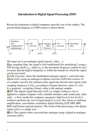
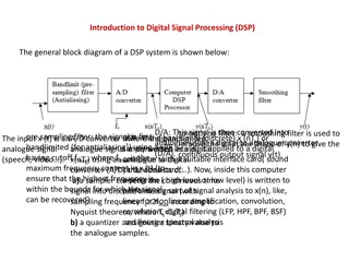
The time domain representation of a second orderARMAfilter is given by the difference equation (1) ?[?] = ?0?[?] + ?1?[? 1] + ?2?[? 2] + ?1?[? 1] + ?2 ?[? 2] This equation expresses the output sequence ?[?] in terms of the input sequence, ?[?], and a set of real coefficients {??}, and {??}. Suppose the input is given by a signal ?(?) corrupted by an additive sinusoidal disturbance, that is ? ? = ?(?) + ???(2??0?) Assume the input is sampled at ?? =44 ??? and that the disturbance frequency is ?0 = ??/4. Your task is to design a second order ARMA filter which stops the disturbance and whose output is a close as possible to the original signal. In order to do this: 1. First, write down the transfer function of such filter, ?(?). 2. Derive the correspondent time domain representation, that is find the values of the coefficients {??}, {??}. 3. Sketch the block diagram representation of the filter.
First, write down the transfer function of such filter, ?(?). ?0 ?? =? First, let us calculate the digital frequency of the disturbance. We have ?0= 2? Recall that the general transfer function of a second order filter can be written as 2. ? ?1 ? ?2 ? ?1 ? ?2 ? = ? Because we want to stop the disturbance, we must have ?(? ??0) =0. This can be achieved by placing the two zeros at ?1= ???0= ? and ?2= ? ??0= ?. We then have to choose the location of the poles and the gain ?. The best choice for the poles is to place them close to the zeros (but within the unit circle for stability). For instance, we can choose ?1= ????0= ??, ?2= ?? ??0= ??, with ? 1 but smaller than 1. We then obtain ? = ??2+ 1 ?2+ ?2 ?(?)?=1= 1, which gives ? =1+?2 The value of the gain can be determined by requiring that So we finally obtain 2. ? =1+?2 ?2+1 ?2+?2(2) 2
Derive the correspondent time domain representation, that is find the values of the coefficients {??}, {??}. By multiplying the factors in Eq. (2), we get ?2 ?1+?2?+?1?2 ?2 ?1+?2?+?1?2=? ? ?1+?2? 1+??1?2? 2 1 ?1+?2? 1+?1?2? 2(3) ? = ? On the other hand, by z-transforming Eq. (1), we get ? =?0+?1? 1+?2? 2 1 ?1? 1 ?2? 2(4) Thus, by comparing Eq. (3) and (4), we get ?0= ?, ?1= ?(?1+ ?2), ?2= ??1?2, and ?1= ?1+ ?2, ?2= ?1?2. In our case that gives ?0=1+?2 2, ?1= 0, ?2=1+?2 , and ?1= 0, ?2= ?2, so 2 ? ? =1 + ?2 + ?2? ? 2 ? ? + ? ? 2 2
Sketch the block diagram representation of the filter. Key points:
? ? =1 + ?2 + ?2? ? 2 ? ? + ? ? 2 2 ? ? 1 + ?2/2 1 + ?2/2 ? ? + D + D ?2
How to implement the filter using Matlab? Think about this question and finish the similar question of assignment.