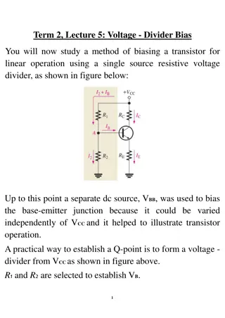
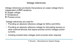
Analysis of NGC Base HV Breakdown Study and Voltage Divider Diagram
The NGC Base HV breakdown study identifies potential workmanship issues affecting sparking in a 60% Neon-40% Argon atmosphere near +2000V. Recommendations include checking and redoing signal and ground attachments, along with hi-potting HV cables to 3000V. Switching to 60% Neon/40% Argon prompts a closer look due to varying breakdown voltages in different gas mixes. The voltage divider diagram further illustrates high and low potential areas in the system, highlighting areas of concern for potential sparking.

Download Presentation

Please find below an Image/Link to download the presentation.
The content on the website is provided AS IS for your information and personal use only. It may not be sold, licensed, or shared on other websites without obtaining consent from the author. Download presentation by click this link. If you encounter any issues during the download, it is possible that the publisher has removed the file from their server.
E N D
Presentation Transcript
NGC Base HV Breakdown Study D. Mack 9/20/21 1
Summary With good QC on the cable attachments, I think these bases should not spark in a 60% Neon-40% Argon atmosphere near +2000V. There is adequate separation, ~8mm, between ground and HV. My threshold for concern is something like 3- 4mm. However, examination of the spare base indicates a workmanship issue on the signal and ground attachments. (Photo at right.) Those all need to be checked and redone as needed. There is a chance that a stray whisker from a ground braid is significantly reducing the 8mm gap in some of the bases. The Argon test tech note at https://hallcweb.jlab.org/doc- private/ShowDocument?docid=794 is very impressive. I learned a lot from it. But with benefit of 20/20 hindsight, i. Only one base was tested, so workmanship issues with the 4 other bases might not have been caught. ii. Tests were done up to +2000V in Argon. To be confident that breakdown would not occur at +2000V in 60%Ne-40%Ar, I estimate the Argon tests would have had to go up to roughly 2500V. Finally, the HV jumper cables inside the tank are also suspects for sparking. Sometimes a stray whisker from the ground braid gets left within a few mm of the HV line. After disconnecting the bases, the HV cables should be hi-potted in air to 3000 V. 2
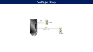
Heres the voltage divider diagram. Low potential areas in blue, and high potential in red. Big blue cap. Big blue cap. Normal NGC signals are negative. In hclog https://logbooks.jlab.org/entry/3901680 , Simona saw a large negative signal followed by a much larger positive signal. Given that we re occasionally blowing FADC channels, perhaps +HV is sparking inside the base to the ground and/or signal lines. 3
This isnt the NGCs first rodeo. Is there something unusual about switching from 100% Argon to 60% Neon/40% Argon? The region we re interested in is in yellow: 1 Atm (760 Torr), and distance scales of 0.1 to 1 cm, hence p*d ~ 380 Torr*cm ish. The Paschen curve predicts the breakdown voltage in a parallel plate capacitor setup. It is an optimistic assessment. I ve seen infrequent sparking in air at ~ 1 kV/mm from sharp solder beads, a factor of 3 below the 3 kV/mm rule of thumb. Gas Paschen Prediction for V_breakdown at 400 Torr-cm (from graph) Max Efield (varies somewhat with distance) Paschen Minimum Gap at 2kV (mm) Paschen Minimum Gap at 2 kV with 3x safety factor (mm) N2 19000 3.8kV/mm 0.5 1.5 Ar 10000 2.0kV/mm 1.0 3 Ne 7000 1.4kV/mm 1.4 4.2 With a neon-rich fill, and realistic geometry, I think we should be concerned if 2 kV appears across any gap less than 3-4mm. There are in principle no such small gaps in this base, as the Argon tech note concluded https://hallcweb.jlab.org/doc-private/ShowDocument?docid=794 . (Unless they re hidden on the far side of the circuit board, or it s not the base at all but a stray whisker in the HV cable.) Let s take a close look at the base. 4
Ive marked low potential areas with blue, and high potential with red. Potential increases systematically with resistor number. Photo at right: This is the socket-divider assembly as it arrives from ET. Because HV and signal cables are not yet attached, it s a good photo to get the lay of the land. (Taken from Fig 2c of the Argon tests tech note.) Those two large blue caps each have one leg near ground, and one leg near full +HV. Definitely a region of interest. (corresponds to a min distance of 8mm for d2 and d3 in the Argon tech note) Half the components are on the other side of the board and can t be examined. (see photo below) The HV line goes to T2. The ground and anode signal lines go to T1 and T3, respectively. Some solder bumps on the periphery are near max potential. And sharp enough to hurt when lightly pressed with a finger. Another region of interest since a grounded casing will be installed. 5
Nice design. Cables are long enough for visual checks and minor work. The red HV cable is very flexible. The black signal co-ax is pretty stiff though, which I ll come back to later. 6
Because the board is recessed in its big blue socket, the near-spikes on the periphery are ~8mm from the grounded metal casing. And they were coated after the board was stuffed.* So I m not too worried about these near-spikes. Let s take off the casing so we can see details better. *The fine print on the circuit diagram says The board is conformally coated with Anti-corona lacquer RS 569-313. Other wording indicates that the big blue caps were added by hand, so the blue cap legs might not be coated. 7
The HV cable (red) is gorgeously terminated. No worries there. The two near-side legs of the big blue capacitors, which are in clear view, are at full +HV. (Btw, from this oblique photo, you can better see the ~2mm height of the near-spikes on the periphery. Since higher resistor numbers mean higher potential, the biggest risk for near-spike sparking would be in the lower right corner.) Ground is on the far-side legs of the big blue capacitors. Looks a little odd. Let s flip this around on the next slide. 8
Ouch. The ground braid has a lot of wild hairs. Not only are there sharp wire ends, but in this example some of them may reduce the gap size from 8mm to 6mm. 9
Different angle, better focus. In a brief test at 2300V in air, I could not make this base spark. That s expected, since an air gap would have to drop to only ~2mm to start sparking infrequently. But these stray ground braid wires are the kind of variable that could cause some bases to have less than 4mm gap and maybe start sparking in a Neon-rich atmosphere. 10
(in hindsight, to get this shot, I m all but breaking off the signal connection) Different angle, better focus. In a brief test at 2300V in air, I could not make this base spark. That s expected, since an air gap would have to drop to only ~2mm to start sparking infrequently. But these stray ground braid wires are the kind of variable that could cause some bases to have less than 4mm gap and maybe start sparking in a Neon-rich atmosphere. 11
A few cable wiggles later, the few copper strands of the signal connection completely broke from the post. I fixed it, arguably with more strain relief and fewer, shorter, sharp wire points. (The black cable is extremely difficult to strip, maybe because it s rated for HV.) I ran this base for an hour at +2200V and am giving it back to Brad. 12
extras 13


 is gorgeously terminated. No worries")