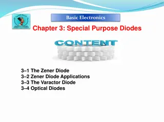
Understanding Zener Diodes: Breakdown Mechanisms and Symbol
A Zener diode is a specialized semiconductor device designed to operate in the reverse breakdown region, with two types of breakdown - avalanche and Zener. Avalanche breakdown occurs at high reverse voltages in both normal and Zener diodes, while Zener breakdown is specific to heavily doped P-N junction diodes. The Zener breakdown exhibits a sharp curve, while avalanche breakdown is not as sharp and occurs in lightly doped diodes. The symbol of a Zener diode includes two terminals - cathode and anode.

Download Presentation

Please find below an Image/Link to download the presentation.
The content on the website is provided AS IS for your information and personal use only. It may not be sold, licensed, or shared on other websites without obtaining consent from the author. Download presentation by click this link. If you encounter any issues during the download, it is possible that the publisher has removed the file from their server.
E N D
Presentation Transcript
Zener Diode A zener diode is a p-n junction semiconductor device designed to operate in the reverse breakdown region. Zener diode is basically like an ordinary PN junction diode but normally operated in reverse biased condition. But ordinary PN junction diode connected in reverse biased condition is not used as Zener diode practically. A Zener diode is a specially designed, highly doped PN junction diode. Zener diode allows electric current in forward direction like a normal diode but also allows electric current in the reverse direction if the applied reverse voltage is greater than the zener voltage. Zener diode is always connected in reverse direction because it is specifically designed to work in reverse direction.
Breakdown in zener diode There are two types of reverse breakdown regions in a zener diode:. 1.Avalanche breakdown 2.zener breakdown
Avalanche breakdown The avalanche breakdown occurs in both normal diodes and zener diodes at high reverse voltage.
Zener breakdown The zener breakdown occurs in heavily doped p-n junction diodes because of their narrow depletion region. When reverse biased voltage applied to the diode is increased, the narrow depletion region generates strong electric field.
Zener Breakdown vs Avalanche Breakdown Zener Breakdown The process in which the electrons move across the barrier from the valence band of p-type material to the conduction band of n-type material is known as Zener breakdown. This is observed in Zener diodes having a Zener breakdown voltage Vz of 5 to 8 volts. Avalanche Breakdown The process of applying high voltage and increasing the free electrons or electric current in semiconductors and insulating materials is called an avalanche breakdown. This is observed in Zener diode having a Zener breakdown voltage Vz greater than 8 volts. The valence electrons are pulled into conduction due to the high electric field in the narrow depletion region. The valence electrons are pushed to conduction due to the energy imparted by accelerated electrons, which gain their velocity due to their collision with other atoms. The increase in temperature increases the breakdown voltage. The increase in temperature decreases the breakdown voltage. The VI characteristics of a Zener breakdown has a sharp curve. The VI characteristic curve of the avalanche breakdown is not as sharp as the Zener breakdown. It occurs in diodes that are highly doped. It occurs in diodes that are lightly doped.
Symbol of zener diode Zener diode consists of two terminals: cathode and anode. In zener diode, electric current flows from both anode to cathode and cathode to anode. The symbol of zener diode is similar to the normal p-n junction diode, but with bend edges on the vertical bar.
VI characteristics of zener diode When forward biased voltage is applied to the zener diode, it works like a normal diode. However, when reverse biased voltage is applied to the zener diode, it works in different manner.
Advantages of zener diode Power dissipation capacity is very high High accuracy Small size Low cost
Applications of zener diode It is normally used as voltage reference Zener diodes are used in voltage stabilizers or shunt regulators. Zener diodes are used in switching operations Zener diodes are used in clipping and clamping circuits. Zener diodes are used in various protection circuits
What is a Voltage Regulator? A voltage regulator is a device that regulates the voltage level. It essentially steps down the input voltage to the desired level and keeps it in that same level during the supply. This ensures that even when a load is applied the voltage doesn t drop. The voltage regulator is used for two main reasons and they are: To vary or regulate the output voltage To keep the output voltage constant at the desired value in spite of variations in the supply voltage. Voltage regulators are used in computers, power generators, alternators to control the output of the plant.
Zener Diode as Voltage Regulator Zener breakdown is a phenomenon where a significant amount of current flows through the diode with a negligible drop in voltage.
Zener diode with a suitable breakdown voltage to work as a voltage regulator Zener diode as a voltage regulator as well as it protects the load from excessive current.
The Zener diode maintains the voltage across it constant in spite of load variations and input voltage fluctuations. Hence we can consider 4 cases to understand the working of a Zener voltage regulator. Case 1 Vo=Vin-IRs Case 2 Case 3 Case 4 Limitations of Zener Voltage Regulator
Voltage Regulators The function of a voltage regulator is to maintain a constant DC voltage at the output irrespective of voltage fluctuations at the input and (or) variations in the load current. In other words, voltage regulator produces a regulated DC output voltage. Voltage regulators are also available in Integrated Circuits (IC) forms. These are called as voltage regulator ICs.
There are two types of voltage regulators Fixed voltage regulator Adjustable voltage regulator
Fixed voltage regulator A fixed voltage regulator produces a fixed DC output voltage, which is either positive or negative. In other words, some fixed voltage regulators produce positive fixed DC voltage values, while others produce negative fixed DC voltage values. 78xx voltage regulator ICs produce positive fixed DC voltage values, whereas, 79xx voltage regulator ICs produce negative fixed DC voltage values.
Afixed positive voltage The input capacitor Ciis used to prevent unwanted oscillations and the output capacitor, C0acts as a line filter to improve transient response.
Adjustable voltage regulator An adjustable voltage regulator produces a DC output voltage, which can be adjusted to any other value of certain voltage range. Hence, adjustable voltage regulator is also called as a variable voltage regulator. The DC output voltage value of an adjustable voltage regulator can be either positive or negative
An unregulated power supply driving a LM 317 voltage regulator IC, which is commonly used. This IC can supply a load current of 1.5A over an adjustable output range of 1.25 V to 37 V.