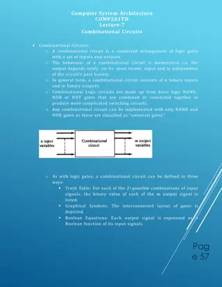
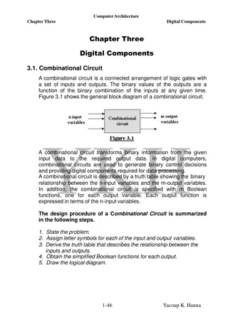
Understanding ALUs and Adders in Computer Architecture
Explore the concepts of Arithmetic Logic Units (ALUs) and adders in computer systems through topics like ALU operations, 1-bit ALU with Add, Or, And operations, 32-bit Ripple Carry Adder, subtraction incorporation, NOR and NAND operations, control lines for different operations, incorporating slt and beq signals in ALUs. Dive deeper into the functionalities and design aspects of these fundamental components in digital systems.

Download Presentation

Please find below an Image/Link to download the presentation.
The content on the website is provided AS IS for your information and personal use only. It may not be sold, licensed, or shared on other websites without obtaining consent from the author. Download presentation by click this link. If you encounter any issues during the download, it is possible that the publisher has removed the file from their server.
E N D
Presentation Transcript
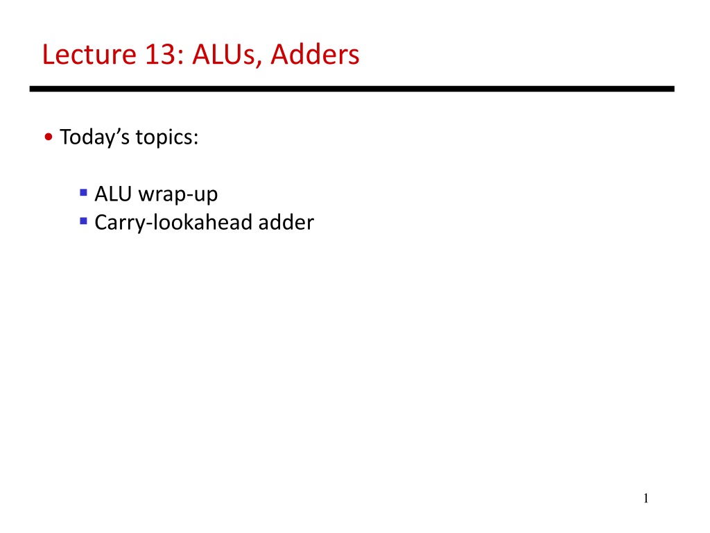
Lecture 13: ALUs, Adders Today s topics: ALU wrap-up Carry-lookahead adder 1
1-Bit ALU with Add, Or, And Multiplexor selects between Add, Or, And operations 2 Source: H&P textbook
32-bit Ripple Carry Adder 1-bit ALUs are connected in series with the carry-out of 1 box going into the carry-in of the next box 3 Source: H&P textbook
Incorporating Subtraction Must invert bits of B and add a 1 Include an inverter CarryIn for the first bit is 1 The CarryIn signal (for the first bit) can be the same as the Binvert signal Source: H&P textbook 4
Incorporating NOR and NAND 5 Source: H&P textbook
Control Lines What are the values of the control lines and what operations do they correspond to? Ai Bn Op AND 0 0 00 OR 0 0 01 Add 0 0 10 Sub 0 1 10 NAND 1 1 01 NOR 1 1 00 6 Source: H&P textbook
Incorporating slt Perform a b and check the sign New signal (Less) that is zero for ALU boxes 1-31 The 31st box has a unit to detect overflow and sign the sign bit serves as the Less signal for the 0th box 7 Source: H&P textbook
Incorporating beq Perform a b and confirm that the result is all zero s 8 Source: H&P textbook
Control Lines What are the values of the control lines and what operations do they correspond to? 9 Source: H&P textbook
Control Lines What are the values of the control lines and what operations do they correspond to? Ai Bn Op AND 0 0 00 OR 0 0 01 Add 0 0 10 Sub 0 1 10 NOR 1 1 00 NAND 1 1 01 SLT 0 1 11 BEQ 0 1 10 10 Source: H&P textbook
Speed of Ripple Carry The carry propagates thru every 1-bit box: each 1-bit box sequentially implements AND and OR total delay is the time to go through 64 gates! We ve already seen that any logic equation can be expressed as the sum of products so it should be possible to compute the result by going through only 2 gates! Caveat: need many parallel gates and each gate may have a very large number of inputs it is difficult to efficiently build such large gates, so we ll find a compromise: moderate number of gates moderate number of inputs to each gate moderate number of sequential gates traversed 11
Computing CarryOut CarryIn1 = b0.CarryIn0 + a0.CarryIn0 + a0.b0 CarryIn2 = b1.CarryIn1 + a1.CarryIn1 + a1.b1 = b1.b0.c0 + b1.a0.c0 + b1.a0.b0 + a1.b0.c0 + a1.a0.c0 + a1.a0.b0 + a1.b1 CarryIn32 = a really large sum of really large products Potentially fast implementation as the result is computed by going thru just 2 levels of logic unfortunately, each gate is enormous and slow 12
Generate and Propagate Equation re-phrased: Ci+1 = ai.bi + ai.Ci + bi.Ci = (ai.bi) + (ai + bi).Ci Stated verbally, the current pair of bits will generate a carry if they are both 1 and the current pair of bits will propagate a carry if either is 1 Generate signal = ai.bi Propagate signal = ai + bi Therefore, Ci+1 = Gi + Pi . Ci 13
Generate and Propagate c1 = g0 + p0.c0 c2 = g1 + p1.c1 = g1 + p1.g0 + p1.p0.c0 c3 = g2 + p2.g1 + p2.p1.g0 + p2.p1.p0.c0 c4 = g3 + p3.g2 + p3.p2.g1 + p3.p2.p1.g0 + p3.p2.p1.p0.c0 Either, a carry was just generated, or a carry was generated in the last step and was propagated, or a carry was generated two steps back and was propagated by both the next two stages, or a carry was generated N steps back and was propagated by every single one of the N next stages 14
Divide and Conquer The equations on the previous slide are still difficult to implement as logic functions for the 32nd bit, we must AND every single propagate bit to determine what becomes of c0 (among other things) Hence, the bits are broken into groups (of 4) and each group computes its group-generate and group-propagate For example, to add 32 numbers, you can partition the task as a tree . . . . . . . . . . . . . . . . . . . . . 15
P and G for 4-bit Blocks Compute P0 and G0 (super-propagate and super-generate) for the first group of 4 bits (and similarly for other groups of 4 bits) P0 = p0.p1.p2.p3 G0 = g3 + g2.p3 + g1.p2.p3 + g0.p1.p2.p3 Carry out of the first group of 4 bits is C1 = G0 + P0.c0 C2 = G1 + P1.G0 + P1.P0.c0 C3 = G2 + (P2.G1) + (P2.P1.G0) + (P2.P1.P0.c0) C4 = G3 + (P3.G2) + (P3.P2.G1) + (P3.P2.P1.G0) + (P3.P2.P1.P0.c0) By having a tree of sub-computations, each AND, OR gate has few inputs and logic signals have to travel through a modest set of gates (equal to the height of the tree) 16
Example Add A 0001 1010 0011 0011 B 1110 0101 1110 1011 g 0000 0000 0010 0011 p 1111 1111 1111 1011 P 1 1 1 0 G 0 0 1 0 C4 = 1 17
Trade-Off Curve Performance Truth table sum-of-products adder, (2, 264) #inputs to each gate # sequential gates gp adder (3, 33) Carry Lookahead GP adder (7, 5) Ripple-Carry adder (64, 2) # sequential gates 18
Carry Look-Ahead Adder 16-bit Ripple-carry takes 32 steps This design takes how many steps? 4 sequential steps 19 Source: H&P textbook