ETM Profiling for Cavity Loss Mitigation Due to Absorbers
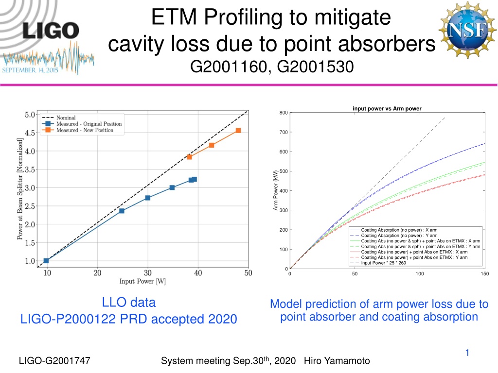
The ETM profiling aims to mitigate cavity loss caused by point absorbers through input power analysis versus arm power. The study includes data on coating absorption, arm power loss predictions, and optimization strategies such as polishing and mirror surface design. The effect of new coatings is compared to optimal shapes, highlighting power and reflectivity results for different surface configurations.

Download Presentation

Please find below an Image/Link to download the presentation.
The content on the website is provided AS IS for your information and personal use only. It may not be sold, licensed, or shared on other websites without obtaining consent from the author. Download presentation by click this link. If you encounter any issues during the download, it is possible that the publisher has removed the file from their server.
E N D
Presentation Transcript
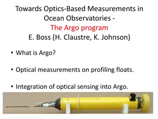
ETM Profiling to mitigate cavity loss due to point absorbers G2001160, G2001530 input power vs Arm power 800 700 600 500 Arm Power (kW) 400 300 200 Coating Absorption (no power) : X arm Coating Absorption (no power) : Y arm Coating Abs (no power & sph) + point Abs on ETMX : X arm Coating Abs (no power & sph) + point Abs on ETMX : Y arm Coating Abs (no power) + point Abs on ETMX : X arm Coating Abs (no power) + point Abs on ETMX : Y arm Input Power * 25 * 260 100 0 0 50 100 150 Input Power (W) LLO data Model prediction of arm power loss due to point absorber and coating absorption LIGO-P2000122 PRD accepted 2020 1 LIGO-G2001747 System meeting Sep.30th, 2020 Hiro Yamamoto
Addition on November 14, 2020 optimized polishing may not be necessary RTL using optimized surface shape vs using coating thickness nonuniformity Latest coating nonuniformity O3 ETM map 10-4 RTL : optimal vs latest coating shape 10-4 RTL : optimal vs O3 ETM maps 4 4 #PA = 0 #PA = 1 #PA = 2 #PA = 3 #PA = 4 #PA = 0 #PA = 1 #PA = 2 #PA = 3 #PA = 4 3.5 3.5 3 3 RTL with latest coating B RTL with O3 ETM map 2.5 2.5 2 2 1.5 1.5 1 1 0.5 0.5 0 0 0 0.5 1 1.5 2 2.5 3 3.5 4 0 0.5 1 1.5 2 2.5 3 3.5 4 RTL with optimal shape A 10-4 RTL with optimal shape A 10-4 2 System meeting Sep.30th, 2020 Hiro Yamamoto 100 cases with #PA = 0~4, random location, random power LIGO-G2001747
polishing design to realize idealistic mirror surface A is idealistic mirror surface Ap is A power term to simplify the RoC specification B is the latest coating shape Bp is to make the polishing easier Polishing [A-B],[Ap- B],[Ap-Bp] are various options of mirror surface polishing 3 LIGO-G2001747 System meeting Sep.30th, 2020 Hiro Yamamoto
Effect of new coating is close to that of optimal shape Power and RTL(ppm) with different ETM surface sph+B : no special polishing, A-B : optimal polishing No point absorber H1X H1Y L1X L1Y power RTL power RTL power RTL. power RTL sphere 262, 62.1 277, 65.4 266, 53.9 266, 55.5 sph+B 262, 63.6 277, 63.8 266, 56.5 266, 57.2 A-B 262, 65.2 277. 65.4 266, 57.8 266, 58.4 A-Bp 262, 70.7 277, 71.0 266, 60.8 266, 61.1 Ap-B 262, 65.6 277, 65.6 266, 57.7 266, 58.4 Ap-Bp 262, 70.5 277, 70.6 266, 60.3 266, 60.7 at 2cm with 30mW One point absorber sphere 257, 211 272, 183 261, 185 261, 195 sph+B 261, 113 275 107 265 99.5 265, 94.9 A-B 261, 98.9 276, 97.2 265, 89.3 265, 86.8 A-Bp 261, 108 275, 107 265, 95.5 265, 92.5 Ap-B 261, 102 276, 98.9 265, 90.5 265, 87.7 Ap-Bp 261, 109 275 107 265, 95.5 265, 92.4 4 LIGO-G2001747 System meeting Sep.30th, 2020 Hiro Yamamoto
new coating shape is closer to optimal shape than O3 ETM O3 map vs new LMA and optimal 10 0 -10 -20 -30 height (nm) -40 -50 -60 -70 -80 Coating thickness B Optimized Surface A ETM15 -90 -100 0 0.02 0.04 0.06 0.08 radius (m) 0.1 0.12 0.14 0.16 5 LIGO-G2001747 System meeting Sep.30th, 2020 Hiro Yamamoto
Power (W) RTL(ppm) wITM,wETM(cm) Performance with multiple PAs # point absorbers Sph - Sph 0 1 2 3 4 all 262 126 264 55.9 263 99.3 262 121 262 110 257 271 5.26, 6.14 5.26, 6.13 5.25, 6.12 5.25, 6.12 5.22, 6.10 5.25, 6.12 ITM - Sph 264 58.4 262 109 262 131 262 121 257 282 262 136 5.26, 6.14 5.25, 6.12 5.25, 6.12 5.24, 6.12 5.22, 6.09 5.25, 6.12 As built O3 ETM maps 264 57.7 263 88.0 263 100 263 94.0 260 179 263 102 5.23, 6.12 5.22, 6.11 5.21, 6.10 5.21, 6.10 5.19, 6.08 5.21, 6.10 Latest coating map (B) Optimal mirror 264 60.2 264 77.6 263 87.8 263 82.3 261 142 263 88.5 5.25, 6.12 5.24, 6.11 5.23, 6.11 5.23, 6.11 5.21, 6.08 5.23, 6.11 264 61.7 264 74.6 263 83.1 263 78.0 262 124 263 83.2 6 LIGO-G2001747 shape (A) 5.23, 6.09 System meeting Sep.30th, 2020 Hiro Yamamoto 5.23, 6.08 5.22, 60.8 5.22, 6.07 5.20, 6.05 5.22, 6.08
Performance with multiple PAs l 200 cases with #PA = 0~4, random location, random power, generated in 4 aLIGO arms l RTL(#PA=3) > RTL(#PA=2) is because the production rate of relevant HOM is less with #PA=3 than #PA=2 in the analyzed case l Sph-sph : ITM is spherical, all other cases use as measured phasemap l Beam size variation is 2% l Polished surface maps are used when real ITM or ETM maps are NOT used 7 LIGO-G2001747 System meeting Sep.30th, 2020 Hiro Yamamoto
Mode analysis Random PA sources in aLIGO arms The optical gains (3rd column), cavity power (2nd column) / production of modes by ETM (1st column), are independent on the number of point absorbers. The ordering of HOM powers in the arm (colored lines in 2nd col) is the same as the ordering of production rates. RTL is determined by the 7th HOM population, so smaller 7th mode in the arm means smaller RTL. Less production of 7th mode with #PA=3 than #PA=2 is the cause of RTL(#PA=3) < RTL(#PA=2). 8 LIGO-G2001747 System meeting Sep.30th, 2020 Hiro Yamamoto
Addition on October 6th l 100 cases of point absorbers are analyzed l 11 FP cases, different map combinations, studied l RoC variations among 4 arms are small l ITM coatings with and without LMA coating masks do make difference l Optical gain vs map combinations No surprise l RTL vs map combinations No surprise 9 LIGO-G2001747 System meeting Sep.30th, 2020 Hiro Yamamoto
11 FP map combinations for 4 arms I, E means coated maps of ITM and ETM Ix, Ex means the maps of uncoated maps (very uniform out to the edge) are used with RoC of the coated surface. This is used to make a surface with specified fall off shape. Corr(a,b) is the fall off correction Differences among four arms for case 1 and 11 are RoC s of coated surfaces 100 sets of point absorbers are generated, and RTL and cavity powers are calculated for 4 arms with these mirror maps. Following are average of events. Plots with and without RH give uncertainty l 1. 2. 3. 4. 5. 6. 7. 8. 9. 10. I - Ex*corr(0.1,30,2e4) 11. Ix *corr(0.1,15) - Ex*corr(0.1,15) Ix - Ex I - Ex I - E I - Ex*corr(0.1,15) I - Ex*corr(0.1,20) I - Ex*corr(0.1,25) I - Ex*corr(0.1,30) I - Ex*corr(0.1,35) I - Ex*corr(0.1,40) l l l l l l 10 LIGO-G2001747 due to RoC correction System meeting Sep.30th, 2020 Hiro Yamamoto
Optical gain 1:no fall off vs 11:both fall off Optical gain without RH Optical gain with RH 35 35 H1X Ix-Ex H1X Ix-Ex both corr(0.1,30) L1X Ix-Ex L1X Ix-Ex both corr(0.1,30) H1X Ix-Ex H1X Ix-Ex both corr(0.1,30) L1X Ix-Ex L1X Ix-Ex both corr(0.1,30) 30 30 25 25 Optical Gain Optical Gain 20 20 15 15 10 10 5 5 0 0 0 5 10 0 5 10 11 mode HGnm n+m mode HGnm n+m LIGO-G2001747 System meeting Sep.30th, 2020 Hiro Yamamoto
Optical gains of 6,7,8th modes shapes of different #PAs are close Optical gain without RH Optical gain with RH 102 102 H1X mode 6 H1X mode 7 H1X mode 8 L1Y mode 6 L1Y mode 7 L1Y mode 8 H1X mode 6 H1X mode 7 H1X mode 8 L1Y mode 6 L1Y mode 7 L1Y mode 8 Optical Gain Optical Gain 101 101 100 100 0 5 10 0 5 10 FP maps cases FP maps cases 12 LIGO-G2001747 System meeting Sep.30th, 2020 Hiro Yamamoto
RTL vs FP maps average of all events RTL vs FP maps without RH RTL vs FP maps with RH 150 150 H1X H1Y L1X L1Y H1X H1Y L1X L1Y 140 140 130 130 120 120 Round trip loss (ppm) Round trip loss (ppm) 110 110 100 100 90 90 80 80 70 70 60 60 50 50 0 5 10 0 5 10 13 FP maps cases FP maps cases LIGO-G2001747 System meeting Sep.30th, 2020 Hiro Yamamoto
RTL for difference #PAs Without RH With RH All cases no PAs #PAs = 1 All cases no PAs #PAs = 1 150 150 150 150 150 150 H1X H1Y L1X L1Y H1X H1Y L1X L1Y RTL (ppm) RTL (ppm) 100 100 100 100 100 100 50 50 50 50 50 50 0 5 10 0 5 10 0 5 10 0 5 10 0 5 10 0 5 10 FP cases FP cases #PAs = 2 #PAs = 3 #PAs = 4 #PAs = 2 #PAs = 3 #PAs = 4 150 150 250 150 150 250 200 200 100 100 150 100 100 150 100 100 50 50 50 50 50 50 0 5 10 0 5 10 0 5 10 0 5 10 0 5 10 0 5 10 14 LIGO-G2001747 System meeting Sep.30th, 2020 Hiro Yamamoto
Addition on October 4tn Spherical surface is based on polished surface map with spherical shape using the RoC of coated surface Comparison of H1 and L1 with the current ITM masks ITM coating mask affects some Optical gain of 7th mode Fall off improve for all cases Small difference affects small Fall off affects in a similar way for all arms Ring heater correction does not change the main effects Different point absorbers cause different effects More analysis coming with more case studies Different correction shapes l l l l l 15 LIGO-G2001747 System meeting Sep.30th, 2020 Hiro Yamamoto
RTL : for A+ ITM with existing mask ETM : sphere vs fall off Fall off effect on RTL with current ITM map ITM maps cross section along x axis 103 10 5 0 RTL with ITM map and ETM with fall off (ppm) -5 -10 height (nm) -15 -20 -25 -30 H1X ITM07 mask 2 H1Y ITM11 mask 1 L1X ITM04 no mask L1Y ITM08 no mask -35 102 -40 -0.15 -0.1 -0.05 0 0.05 0.1 0.15 radius (m) This fall off helps to reduce RTL 102 103 RTL with ITM map and ETM sphere (ppm) 16 LIGO-G2001747 System meeting Sep.30th, 2020 Hiro Yamamoto
Effect of fall off edge on Optical Gain of 7th mode 102 In the future, H1X H1Y L1X L1Y 7th mode Optical Gain with fall off (0.1,30) on ITM/ETM When both ITM and ETM are polished both are spherical vs with fall off 101 Effect of fall off edge on RTL 103 H1X H1Y L1X L1Y RTL with fall off(0.1,30) on ITM/ETM (ppm) 100 100 101 102 7th mode Optical Gain with sphere on ITM/ETM 102 RH effect on RTL 103 H1Y without RH H1X with RH L1Y without RH L1Y with RH RTL with fall off(0.1,30) on ITM/ETM (ppm) 102 RTL with sphere on ITM/ETM (ppm) 103 The difference among 4 cases are caused by RoCs of mirrors Effects of fall off on optical gain and RTL are the same Gains and loss can be different from case 102 17 LIGO-G2001747 by case, depending on PA populations 102 RTL with sphere on ITM/ETM (ppm) 103 System meeting Sep.30th, 2020 Hiro Yamamoto
Cause and effect of point absorbers on test masses Lens vs Surface distrotion with 0.1W in point or coating on ITM (A) Point abs 450 Mirror Point absorption on mirror surface causes thermal distortion of the surface and substrate Many HOMs are induced on reflection FP cavity aLIGO arm is close to resonance of TEMnm, n+m=7, and this mode is amplified in the cavity, HOM has long power tail and induces large RTL aLIGO IFO, DRFPM Large RTL reduces PRG Curvature mismatch of fields from two arms reduces PRG RTL of FP PRG of full DRFPM Lens by Point Abs 15 x Surface by Point Abs Lens by Coating Abs 15 x Surface by Coating Abs 400 350 (A) 300 Optical path (nm) 250 200 150 100 coating abs 50 0 -20 -15 -10 -5 0 5 10 15 20 radius (cm) (B) mod(gouy00*N,pi)/pi ( - 1 ) 0.5 (B) 0.45 0.4 0.35 phase from resonance (C) 0.3 0.25 0.2 0.15 LTR vs PRG 60 0.1 X (2cm) 0~50mW X (2cm), Y (2cm) 10~50mW X (2cm), Y (2cm,P<0) 10~50mW X (2cm), Y(-2cm) 10~50mW X (2cm) 0~50mW w/TM map X (2cm), Y (2cm) 10~50mW w/TM map X (2cm), Y (2cm,P<0) 10~50mW w/TM map X (2cm), Y(-2cm) 10~50mW w/TM map X (0~5cm) 30mWexp(-2r2) X (2cm), Y (-4cm~4cm) 30mWexp(-2r2) X (2cm), Y (0,0~4cm) 30mWexp(-2r2) CC PRG( (RTLX+RTLY)/2 ) * 0.9 (D) (D) 0.05 50 0 0 1 2 3 4 5 6 7 8 9 10 n+m in HGnm Clipping loss pf cavity field with one PA (C) 100 40 10-1 PRG 30 10-2 7th mode 15% 20 10-3 Loss 10-4 10 10-5 0 50 100 150 200 250 300 350 10-6 18 (RTLX+RTLY)/2 (ppm) LIGO-G2001747 System meeting Sep.30th, 2020 Hiro Yamamoto 10-7 0 1 2 3 4 5 6 7 8 9 10 mode
Test Mass surface profiling to suppress higher order modes PRG is compromised by point absorbers on test masses Higher order mode excitation by point absorber on a mirror Large roundtrip loss due to long tails of resonating higher order modes Two ways to reduce point absorber effects Suppress the excitation of higher order mode by point absorbers Suppress the resonance condition of the 7th order mode A mirror surface profile suppressing the 7th mode resonance (motivated by LMA coating, next page) ?2 2 ?? cor r ,cor r = exp a ?2 b ?4, ? = 0.1,? = 30 at central region : RoC=Rm, at peripheral region : RoC > Rm Low order mode (00) : spherical surface with RoC=Rm High order mode (7th) : RoC change from central to edge, affects resonance condition A. B. C. ??????? ? = 0 20 correction (nm) LG00 amp LG31 amp ?/?2 Surface height (nm) ????? ??? -100 10 19 LIGO-G2001747 System meeting Sep.30th, 2020 Hiro Yamamoto -200 0 -0.2 -0.15 -0.1 -0.05 0 0.05 0.1 0.15 0.2 radius (m)
Map specifications and performance Functional form motivated by Diffraction losses of a Fabry-Perot cavity with nonidentical non-spherical mirrors" by Poplavskiy, Matsko, Yamamoto, Vyatchanin Article reference: JOPT-107582.R1 ?2 ???2+??4 2 ?? ETM Map and Fit ITM - r2/2/1934m ETM - r2/2/2245m 10 5 5 ITM07 HX ITM11 HY ITM04 LX ITM08 LY ETM13 HX ETM16 HY ETM10 LX ETM15 LY 0 -10 -20 0 0 -30 height (nm) height (nm) height (nm) -40 -50 -60 -5 -5 -70 -80 ETM15 RoC=2245m ETM06 RoC=2245m Fit(0.1,30) Fit(0.1,15) -90 -100 -10 -10 -0.15 -0.1 -0.05 0 0.05 0.1 0.15 -0.15 -0.1 -0.05 0 0.05 0.1 -0.15 -0.1 -0.05 0 0.05 0.1 x (m) x (m) x (m) 20 LIGO-G2001747 System meeting Sep.30th, 2020 Hiro Yamamoto
What are studied 1) Does this shape suppress 7th mode efficiently 2) Performance when there is no point absorber 3) Performance when there is coating absorption 4) Performance when beam is tilted to reduce the point absorber effect 5) Requirement on polishing and coating 21 LIGO-G2001747 System meeting Sep.30th, 2020 Hiro Yamamoto
* Stationary field by FFT * Field is mode-expanded using standard HG or LG FFT simulation ITM E ETM standard HG or LG ?????2 ? = ??? ???? ?????= ??? ???? ???? = ?>??????? ?,? ?+?=???? Power to ETM in FP with coating abs(0.35W), no PA Power to ETM in FP with coating abs(0.35W), PA(30mW) on ETM 106 106 104 104 102 102 Power density (W/m2) Power density (W/m2) 100 100 10-2 10-2 10-4 10-4 Totoal power 6th mode (0.7ppm) 7th mode (0.2ppm) 8th mode (1.4ppm) mirror edge mirror edge Totoal power 6th mode (0.5ppm) 7th mode (7.6ppm) 8th mode (1.1ppm) mirror edge mirror edge 10-6 10-6 10-8 10-8 -0.25 -0.2 -0.15 -0.1 -0.05 0 0.05 0.1 0.15 0.2 0.25 -0.25 -0.2 -0.15 -0.1 -0.05 0 0.05 0.1 0.15 0.2 0.25 x axis (m) 22 x axis (m) LIGO-G2001747 System meeting Sep.30th, 2020 Hiro Yamamoto
Does this shape suppress 7th mode efficiently Optical gain 7thmode gain is suppressed but mode Power on Reflection for 1W input 10-4 Power (W) 10-5 10-6 0 1 2 3 4 5 6 7 8 9 10 11 No map ETM15 map Fit(0.1,30) Fit(0.1,15) Clipping loss mode Power in FP cavity (1W to FP, L1 Y arm) Power (W) 10-2 10-4 Mirror cross section 10 0 1 2 3 4 5 6 7 8 9 10 11 no map ETM15 fit(0.1,30) fit(0.1,15) No map ETM15 map Fit(0.1,30) Fit(0.1,15) Optical gain of modes (L1 Y arm) : 2x10⁴ for 00 0 102 -10 Optical gain height (nm) -20 100 -30 -40 10-2 0 1 2 3 4 5 6 7 8 9 10 11 23 -50 -0.15 -0.1 -0.05 0 0.05 0.1 0.15 LIGO-G2001747 System meeting Sep.30th, 2020 Hiro Yamamoto Mode (n+m) radius(m)
mode Power on Reflection for 1W input 10-4 Power (W) 10-5 10-6 0 1 2 3 4 5 6 7 8 9 10 11 No map ETM15 map Fit(0.1,30) Fit(0.1,15) mode Power in FP cavity (1W to FP, L1 Y arm) Power (W) 10-2 Optical gain with various ETM surface profile 10-4 0 1 2 3 4 5 6 7 8 9 10 11 No map ETM15 map Fit(0.1,30) Fit(0.1,15) Optical gain of modes (L1 Y arm) : 2x10⁴ for 00 102 Optical gain 100 10-2 0 1 2 3 4 5 6 7 8 9 10 11 Mode (n+m) 24 LIGO-G2001747 System meeting Sep.30th, 2020 Hiro Yamamoto
mode Power on Reflection for 1W input 10-4 Power (W) 10-5 RTL = gain x clipping loss 10-6 0 1 2 3 4 5 6 7 8 9 10 11 No map ETM15 map Fit(0.1,30) Fit(0.1,15) mode Power in FP cavity (1W to FP, L1 Y arm) 15%,30ppm clipping loss (%), absolute loss (ppm) 6%,4ppm Power (W) 10-2 39%,4ppm 15%,5ppm 27%,1ppm 10-4 0 1 2 3 4 5 6 7 8 9 10 11 No map ETM15 map Fit(0.1,30) Fit(0.1,15) Optical gain of modes (L1 Y arm) : 2x10⁴ for 00 25 LIGO-G2001747 102 System meeting Sep.30th, 2020 Hiro Yamamoto Optical gain 100 10-2 0 1 2 3 4 5 6 7 8 9 10 11 Mode (n+m)
Does this shape suppress 7th mode efficiently Dependence on mirror maps RTL with one PA on ETM (2cm, 30mW) Fit : a=0.1, b=30 00 loss = 1 - 00 power on ETM with PA / without PA ITM and ETM maps ITM map ETM no map ITM map ETM cor (0.1,30) ITM no map ETM cor(0.1,30) TEM00 gain loss Current performance (PA / no PA) 148 / 58 Larger loss w/o ETM map Performance with new ETM maps (O4) Smooth ITM (O5) with new ETM maps (O4) Loss of the signal (fit / as is)pp 0.5% / 1.3% H1 X arm ITM07-ETM13 195 95 91 H1 Y arm ITM11-ETM16 140 / 59 190 96 90 0.5% / 1.2% L1 X arm ITM04-ETM10 137 / 57 180 88 91 0.5% / 1.1% L1 Y arm ITM08-ETM15 120 / 58 193 87 90 0.5% / 0.9% 26 LIGO-G2001747 System meeting Sep.30th, 2020 Hiro Yamamoto
one vs two PAs dE = E-TEM00 dRTL = RTL RTL0, RTL0 = RTL(without map and absorber) = 48ppm dEE 3cm one absorber 10mW at x=2cm, y=0 No mirror maps dRTL=10ppm one absorber 10mW at x=2cm, y=0 L1 x arm maps dRTL= 17ppm two absorbers 10mW at 2cm & -2cm L1 x arm maps dRTL= 11ppm dEI 20cm 27 LIGO-G2001747 System meeting Sep.30th, 2020 Hiro Yamamoto
Does this shape suppress 7th mode efficiently Multiple point absorbers Random locations and powers #PAs : 0~4 poisson (ave=2) Locations(x,y) : normal (sig=3cm) Power( r ) = normal( 30mW)*exp(-2r2/w^2) ?2 2 ??exp( a ?2-b ?4- c ?8) ???? ?,?,? = LLO Y arm ITM:phase map ETM:uncoated map +correction 60 60 50 50 1 40 40 0.995 PRG with correction 0.99 0.985 30 30 height correction 0.98 0.975 20 20 0.97 0.965 0.96 [0.1,15] [0.1,30] [0.1,30,0,20000] 10 10 #PA=1 #PA=2 #PA=3 #PA=4 0.955 0 0.02 0.04 0.06 0.08 radius (m) 0.1 0.12 0.14 0.16 0.18 0.1, 30, 0 0.1, 30, 20000 0 0 28 0 20 40 60 0 20 40 60 LIGO-G2001747 System meeting Sep.30th, 2020 Hiro Yamamoto PRG without corr
Performance when there is no point absorber Effect of edge fall off shape when there is no PA but with coating absorption ITM : phasemap as is ETM : uncoated map + fall off shape exp(-a r2 b r4) LHO X 262 / 62 262 / 65 261 / 57 260 / 64 262 / 61 262 / 69 LHO Y 277 / 63 277 / 65 276 / 57 275 / 66 277 / 62 277 / 71 LLO X 266 / 54 266 / 57 265 / 54 264 / 60 266 / 55 266 / 58 LLOY 266 / 55 266 / 58, 266 / 58 265 / 55 264 / 60, 264 / 59 266 / 56 266 / 59, 266 / 60 No thermal (power/RTL) Coating abs No RH Coating abs RH corr Poorman s ring heater Arm power (W) / RTL (ppm) without fall off Arm power (W) / RTL (ppm) with fall off Arm power (W) / RTL (ppm) with ETM15 map ? = ?? ?2 (1 ?? 1 ?0) 4 29 LIGO-G2001747 System meeting Sep.30th, 2020 Hiro Yamamoto
Performance when there is coating absorption Point absorber (2cm,30mW) on ETM, Coating absorption(700kW,0.5ppm), Ring heater (HR RoC) Thermal aberration by coating absorption by Hello-Vinet Ring heater nullifies LG(1,0) excitation by HR RoC change LLO PRG : without RH 30.3, with RH 28.5 102 50 PointAbs, no thermal, no correction 170ppm PointAbs, no thermal, Shape(0.1,30) 90ppm PointAbs, 700kW*0.5ppm, no corr 105ppm PointAbs, 700kW*0.5ppm, Shape(0.1,30) 92ppm PointAbs, 700kW*0.5ppm, w/ RH no correction 110ppm PointAbs, 700kW*0.5ppm, w/ RH Shape(0.1,30) 176ppm PointAbs, no thermal, no correction 170ppm PointAbs, no thermal, Shape(0.1,30) 90ppm PointAbs, 700kW*0.5ppm, no corr 105ppm PointAbs, 700kW*0.5ppm, Shape(0.1,30) 92ppm PointAbs, 700kW*0.5ppm, w/ RH no correction 110ppm PointAbs, 700kW*0.5ppm, w/ RH Shape(0.1,30) 176ppm 40 101 30 20 100 10 Mode power Xsec (nm) 10-1 0 -10 10-2 -20 Coating thermal RH correction Edge shape -30 10-3 -40 10-4 -50 0 1 2 3 4 5 6 7 8 9 10 11 -0.15 -0.1 -0.05 0 0.05 0.1 0.15 Mode X axis (m) 30 LIGO-G2001747 System meeting Sep.30th, 2020 Hiro Yamamoto
Performance when there is coating absorption Thermal effect in DRFPM When or how to use RH LLO : ITM coated map, ETM uncoated map + corr(0.1,30) case Coating abs 0 PA on EY 0 Correction ETM no RH (ITM,ETMX) no RH (ETMY) no PRG 1 53 2 vs 4 0 30mW no no no 27 3 vs 5~7 4 0.35W 30mW no no no 33 0 30mW 0.1,30 no no 44 5 0.35W 30mW 0.1,30 no no 33 6 0.35W 30mW 0.1,30 yes no 27 7 0.35W 30mW 0.1,30 yes yes 23 31 LIGO-G2001747 System meeting Sep.30th, 2020 Hiro Yamamoto
Performance when beam is tilted to reduce the point absorber effect Beam offset on ETM ITM : ITM08 coated phase map ETM : ETM15 uncoated phase map with correction (0.1,30) Coating absorption on ITM and ETM, 0.35W each Point absorber on ETM at -20mm from center (power=30mW exp(-2 r2 / 6.2cm2)) Tilt ETM to make the resonating beam position on ETM to have offset, 0~40mm (opposite to point absorber), keeping the beam on ITM to be centered RH correction calculated with beam at the center of ETM l l l l l l Input beam is tilted to make proper mode matching between the input and the resonating cavity mode Mode expansion using the cavity axis 8 cases compared Coating absorption off / on Point absorber off / on shape correction off / on l l l 32 LIGO-G2001747 System meeting Sep.30th, 2020 Hiro Yamamoto
Performance when beam is tilted to reduce the point absorber effect Power and RTL vs offset Roundtrip loss vs ETM beam center offset 00 mode power vs ETM beam center offset 200 268 coat=0,point=0,no corr coat=0,point=0,w/ corr coat=0.35W,point=0,no corr coat=0.35W,point=0,w/ corr coat=0,point=30mW,no corr coat=0,point=30mW,w/ corr coat=0.35W,point=30mW,no corr coat=0.35W,point=30mW,w/ corr 266 150 264 Roundtrip loss (ppm) Power (W) 262 100 260 coat=0,point=0,no corr coat=0,point=0,w/ corr coat=0.35W,point=0,no corr coat=0.35W,point=0,w/ corr coat=0,point=30mW,no corr coat=0,point=30mW,w/ corr coat=0.35W,point=30mW,no corr coat=0.35W,point=30mW,w/ corr 258 50 256 0 5 10 15 20 25 30 35 40 0 5 10 15 20 25 30 35 40 Beam offset on ETM (mm) Beam offset on ETM (mm) solid : flat map, dashed : fall off red and purple : no coating abs blue and cyan : with coating abs red and blue : no point abs purple and cyan : with point abs 7th mode power vs ETM beam center offset 10-1 10-2 Power (W) 10-3 coat=0,point=0,no corr coat=0,point=0,w/ corr coat=0.35W,point=0,no corr coat=0.35W,point=0,w/ corr coat=0,point=30mW,no corr coat=0,point=30mW,w/ corr coat=0.35W,point=30mW,no corr coat=0.35W,point=30mW,w/ corr 10-4 33 LIGO-G2001747 System meeting Sep.30th, 2020 Hiro Yamamoto 0 5 10 15 20 25 30 35 40 Beam offset on ETM (mm)
Extra factors Polishing spec = idealistic surface all possible deformations Coating stress effect on RoC (T970176, T050057) Waiting for LMA report Intrinsic coating non uniformity (T2000398) Waiting for LMA report Deformation by gravity (T050184) Negligible Polishing requirement In radius > 8cm, height variation less 10% Anything else? l l l l l l 34 LIGO-G2001747 System meeting Sep.30th, 2020 Hiro Yamamoto
Summary The surface shape correction of test mass to reduce the thickness at the edge by O(1%) works OK The effect by a single absorber seems to be improved by a factor When the thermal deformations by coating absorption and point absorber mix badly, a careful ring heater correction will be necessary and this shape does not help, nor does it harm. Nominal ring heater to restore the central region curvature adds to much curvature at the edge. Another ring heater to handle the edge may be necessary. l l l l 35 LIGO-G2001747 System meeting Sep.30th, 2020 Hiro Yamamoto
Answer to recommendations For this case, what is the eigenfrequency for the 6th & 7th order modes (delta_f from the TEM00 mode)? df is not all to determine the mode gain loss or width or coupling to other modes matter l 0.3 7th Sph, A=50cm / 1000 : df=1864Hz 7th Sph A=32.6cm : df=1064Hz 7th Sph+B, A=32.6cm : df=-1486Hz 6th Sph A=32.6cm / 10 : df=6812Hz 6th Sph+B, A=32.6cm / 10 : df=4712Hz 0.25 Analytic df for 6th mode 0.2 Power 0.15 0.1 This matches with analytic calculation for the 7th mode 0.05 0 36 -4000 -2000 0 2000 RF (Hz) 4000 6000 8000 LIGO-G2001747 System meeting Sep.30th, 2020 Hiro Yamamoto
Answer to recommendations G2001747-v3, slide 32, upper right plot. Is there any understanding why the RTL for the solid purple curve is lower than for the solid red curve for offsets greater than 2.5 cm ? A : there was a bug to setup a FP cavity with offset. Needs to be redone. Also why is the RTL for the dashed cyan curve higher than for the solid cyan at zero offset? A : see the answer in the last page. The thermal bump by the coating absorption distorts the field and the edge fall off does not work as is naively expected. As the beam is moved, does the absorbed power stay the same, or decrease as it s moved away from the PA? A : Power changes as exp(-2 d2 / w2) where d is the distance between the beam and the point absorber. l l l 37 LIGO-G2001747 System meeting Sep.30th, 2020 Hiro Yamamoto
Answer to recommendations Can you comment on the benefit of retaining or removing the slight spherical aberration, induced by the coating, using a custom polish? Simply filling the central dip harms => larger 6th mode gain RTL(flat) is 10% larger than RTL(B) l Cavity gain : LLO Y arm Mode power vs polish shape : LLO Y arm 10-9 103 104 1 B asis B flat in r<6cm B flat center B RoC correction flat center RoC correction B flat center 102 0 Curvature correction flattening 102 100 -1 101 Mode ppower Mode power height (m) 10-2 -2 100 10-4 -3 10-1 10-6 -4 10-8 -5 10-2 0 2 4 6 8 10 12 0 0.01 0.02 0.03 0.04 0.05 0.06 0.07 0.08 0.09 0.1 0 2 4 6 8 10 12 Modes radius (m) modes 38 LIGO-G2001747 System meeting Sep.30th, 2020 Hiro Yamamoto
Answer to recommendations From G2001747-v3 page 32 - Are labels swapped? Cyan with corr is worse than without at center alignment. A: labels are not swapped. These are plots of ITM and ETM surfaces with 0.35W coating absorption. Bump at the center by the absorption affects the cavity mode a lot. Modes with 0.35W coating abs l 10-7ETM without fall off 10-7 ETM with fall off 1 1 without RH with RH without RH with RH 0.5 0.5 heigt (m) 0 0 -0.5 -0.5 103 no correc, no RH fall off corr, no RH no correc, with RH fall off, with RH -1 -1 -0.1 0 0.1 -0.1 0 0.1 102 radius (m) 10-7ITM without fall off 10-7ITM with edge fall off 101 1 1 mode power 100 0.5 0.5 10-1 0 0 10-2 -0.5 -0.5 10-3 -1 -1 -0.1 0 0.1 -0.1 0 0.1 10-4 0 2 4 6 8 10 12 Modes Also plots on slide 2 - are the axes labels swapped? A : Yes, axes are swapped l 39 LIGO-G2001747 System meeting Sep.30th, 2020 Hiro Yamamoto
Cases studied 100 events generated, up to 4 point absorbers on ETM, at random locations with random power Prand, each PA absorbs Prand*exp(- 2r2/w2) (r is distance between the beam at center and the individual PA). 1. ITM (measured map and measured RoC) + ETM sphere (polished surface + measured RoC of the arm) 2. ITM + ETM as measured map and measured RoC 3. ITM + ETM sphere + coating thickness B 4. ITM + ETM sphere + B + 200mW coating absorption 5. ITM + ETM sphere + B + 200mW + ring heater RoC correction 40 LIGO-G2001747 System meeting Sep.30th, 2020 Hiro Yamamoto
ETM surfaces 41 LIGO-G2001747 System meeting Sep.30th, 2020 Hiro Yamamoto
beam size / MM val - 1 : #PA = 1 0.005 Beam size measured beam size / modal model value - 1 0 -0.005 -0.01 -0.015 -0.02 -0.025 -0.03 H1X ITM 5.27cm H1X ETM 6.14cm H1Y ITM 5.26cm H1Y ETM 6.14cm L1X ITM 5.26cm L1X ETM 6.15cm L1Y ITM 5.26cm L1Y ETM 6.13cm #PA = 1 -0.035 -0.04 -0.045 beam size / MM val - 1 : #PA = 0 -0.05 0.005 beam size / MM val - 1 : #PA = 2 1 1.5 2 2.5 3 3.5 4 4.5 5 0.005 0 -0.005 -0.01 0 -0.015 wFFT / wMM - 1 -0.02 -0.005 -0.025 -0.03 #PA = 2 -0.035 -0.01 -0.04 -0.045 -0.05 0.005 beam size / MM val - 1 : #PA = 3 1 1.5 2 2.5 3 3.5 4 4.5 5 -0.015 1:sphere, 2:O3 ETM, 3:sph+B, 4:sph+B+0.2Wabs, 5:sph+B+0.2Wabs+RH wFFT / wMM - 1 0 -0.005 -0.02 #PA = 0 -0.01 -0.015 wFFT / wMM - 1 -0.02 -0.025 -0.025 -0.03 #PA = 3 -0.035 -0.03 -0.04 -0.045 H1X ITM 5.27cm H1X ETM 6.14cm H1Y ITM 5.26cm H1Y ETM 6.14cm L1X ITM 5.26cm L1X ETM 6.15cm L1Y ITM 5.26cm L1Y ETM 6.13cm -0.035 -0.05 1 1.5 2 2.5 3 3.5 4 4.5 5 beam size / MM val - 1 : #PA = 4 1:sphere, 2:O3 ETM, 3:sph+B, 4:sph+B+0.2Wabs, 5:sph+B+0.2Wabs+RH 0.005 0 -0.04 -0.005 -0.01 -0.015 wFFT / wMM - 1 -0.045 -0.02 -0.025 -0.03 -0.05 -0.035 #PA = 4 1 1.5 2 2.5 3 3.5 4 4.5 5 -0.04 1:sphere, 2:O3 ETM, 3:sph+B, 4:sph+B+0.2Wabs, 5:sph+B+0.2Wabs+RH -0.045 42 -0.05 1 1.5 2 2.5 3 3.5 4 4.5 5 1:sphere, 2:O3 ETM, 3:sph+B, 4:sph+B+0.2Wabs, 5:sph+B+0.2Wabs+RH LIGO-G2001747 System meeting Sep.30th, 2020 Hiro Yamamoto
RTL, #PAs and effect of B RTL vs #point absorbers 250 H1X sphehre+B H1X sphere H1Y sphere+B H1Y sphere L1X sphere+B L1X sphere L1Y sphere+B L1Y sphere 200 Roundtrip Loss (ppm) 150 100 50 0 0.5 1 1.5 2 2.5 3 3.5 4 43 #point absorbers LIGO-G2001747 System meeting Sep.30th, 2020 Hiro Yamamoto
Roundtrip loss of O3 four arms : #PA = 0 70 H1X H1Y L1X L1Y More on RTL vs shape 68 66 64 Roundtrip Loss (ppm) 62 60 58 56 54 RTL(#PA=0) 52 50 1 1.5 2 2.5 3 3.5 4 4.5 5 1:sphere, 2:O3 ETM, 3:sph+B, 4:sph+B+0.2Wabs, 5:sph+B+0.2Wabs+RH Increase Roundtrip loss of O3 four arms : RTL(#PA=2)-RTL(#PA=0) 90 H1X H1Y L1X L1Y Increase Roundtrip loss of O3 four arms : RTL(#PA=1)-RTL(#PA=0) 80 90 70 H1X H1Y L1X L1Y Increase of Roundtrip Loss (ppm) 60 80 50 40 30 70 20 Increase of Roundtrip Loss (ppm) RTL(#PA=2)-RTL(0) 10 RTL(#PA=1)-RTL(#PA=0) 60 0 1 1.5 2 2.5 3 3.5 4 4.5 5 1:sphere, 2:O3 ETM, 3:sph+B, 4:sph+B+0.2Wabs, 5:sph+B+0.2Wabs+RH Increase Roundtrip loss of O3 four arms : RTL(#PA=3)-RTL(#PA=0) 90 H1X H1Y L1X L1Y 80 50 RTL(#PA=3)-RTL(0) 70 Increase of Roundtrip Loss (ppm) 60 40 50 40 30 30 20 10 0 20 1 1.5 2 2.5 3 3.5 4 4.5 5 Increase Roundtrip loss of O3 four arms : RTL(#PA=4)-RTL(#PA=0) 1:sphere, 2:O3 ETM, 3:sph+B, 4:sph+B+0.2Wabs, 5:sph+B+0.2Wabs+RH H1X H1Y L1X L1Y 200 180 160 10 Increase of Roundtrip Loss (ppm) 140 120 100 0 1 1.5 2 2.5 3 3.5 4 4.5 5 80 1:sphere, 2:O3 ETM, 3:sph+B, 4:sph+B+0.2Wabs, 5:sph+B+0.2Wabs+RH 60 40 RTL(#PA=4)-RTL(0) 44 20 LIGO-G2001747 System meeting Sep.30th, 2020 Hiro Yamamoto 0 1 1.5 2 2.5 3 3.5 4 4.5 5 1:sphere, 2:O3 ETM, 3:sph+B, 4:sph+B+0.2Wabs, 5:sph+B+0.2Wabs+RH
Optical Gains vs Modes HOM gains are weakly depends on #PAs Optical gain in H1X : HOM gains are independent on #PAs Optical gain in L1X : HOM gains are independent on #PAs 102 102 sph+B, #PA=1 Sph+B, #PA=2 Sph+B, #PA=3 Sph+B, #PA=4 sph, #PA=1 Sph, #PA=2 Sph, #PA=3 Sph, #PA=4 sph+B, #PA=1 Sph+B, #PA=2 Sph+B, #PA=3 Sph+B, #PA=4 sph, #PA=1 Sph, #PA=2 Sph, #PA=3 Sph, #PA=4 101 101 Mode power Mode power 100 100 10-1 10-1 0 2 4 6 8 10 12 0 2 4 6 8 10 12 Modes Modes 45 LIGO-G2001747 System meeting Sep.30th, 2020 Hiro Yamamoto
Mode gain vs shape (#PA=1) Mode Gain vs Shapes 102 H1X HG6 H1X HG7 H1X HG8 L1X HG6 L1X HG7 L1X HG8 101 optical gain 100 10-1 1 1.5 2 2.5 3 3.5 4 4.5 5 46 1:sphere, 2:O3 ETM, 3:sph+B, 4:sph+B+0.2Wabs, 5:sph+B+0.2Wabs+RH LIGO-G2001747 System meeting Sep.30th, 2020 Hiro Yamamoto
Offset dependence PA absorption of 30mW x exp(-2r2/w2) is placed at - 2cm, where r is the distance between the PA and the beam center Beam center is moved away from the PA The center of the 200mW thermal bump by coating is the location of the beam on EM Mode is calculated using the cavity axis as z axis l l l l 47 LIGO-G2001747 System meeting Sep.30th, 2020 Hiro Yamamoto
RTL vs offset RTL of H1X arm vs beam center Mode power vs beam offset H1X arm 300 103 sph no RH sph with RH B no RH B with RH B 200mW no RH B 200mW with RH B 200mW PA(30mW@-2cm) no RH B 200mW PA(30mW@-2cm) with RH B + 200mW no RH at y=0cm B + 200mW with RH at y=0cm B + 200mW no RH at y=4cm B + 200mW with RH at y=4cm B + 200mW PA(30mW@-2cm) no RH at y=0cm B + 200mW PA(30mW@-2cm) with RH at y=0cm B + 200mW PA(30mW@-2cm) no RH at y=4cm B + 200mW PA(30mW@-2cm) with RH at y=4cm 102 250 101 200 100 mode power RTL (ppm) 150 10-1 10-2 100 10-3 50 10-4 0 10-5 0 0.5 1 1.5 2 beam center (cm) 2.5 3 3.5 4 4.5 5 0 2 4 6 8 10 12 Modes 4cm 0cm vs 4cm 0cm 48 LIGO-G2001747 System meeting Sep.30th, 2020 Hiro Yamamoto


")


")