Quality Control and Testing Procedures for Superconducting Radiofrequency Cavities
The presentation highlights the rigorous processes involved in qualifying superconducting radiofrequency (SRF) cavities for high-performance applications. Each cavity undergoes a detailed qualification process, including BCP treatment, electropolishing, and high-pressure rinsing, to ensure optimal performance. Stringent testing at low temperatures and clean room environments is crucial for meeting operating gradients and Q0 requirements. The comparison of cavity behaviors and onset gradients provides valuable insights into the performance characteristics of the cavities. Quality control measures, such as noise floor determination and onset gradient analysis, are essential in evaluating cavity performance and ensuring reliable operation.
- Quality Control
- Superconducting Radiofrequency Cavities
- Testing Procedures
- Performance Evaluation
- Quality Assurance

Download Presentation

Please find below an Image/Link to download the presentation.
The content on the website is provided AS IS for your information and personal use only. It may not be sold, licensed, or shared on other websites without obtaining consent from the author. Download presentation by click this link. If you encounter any issues during the download, it is possible that the publisher has removed the file from their server.
E N D
Presentation Transcript
I did not perform any data analysis or create any plots used in this talk
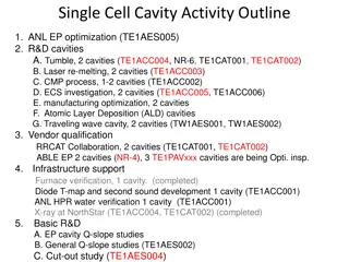
Cavities must deliver an Average Maximum Operating gradient of 19.2 MV/m with average Q0 of 7.2E9 at 2.07 K 96% exceeded requirement Each cryomodule contains a string of eight 7-cell low-loss SRF 1497 MHz cavities Each Cavity undergoes an rigorous qualification process 160 M BCP 600 C Bake 24 hours Hydrogen removal- Eliminates Q0 disease 30 M Electropolish Reduce Q0 Slope Multiple High Pressure Rinses 120 C Bake for 24 hours Vertical Test at 2.07 K Cavity String assembled in a Class 1000-100 Clean room
DecaRad BL Ret BL Sup Top Center WG8 WG2 WG4/5 WG1 WG3 WG6 WG7 OctiRad BL Sup BL Ret Top Center WG1/2 WG4/5/6 WG7/8 WG3/4/5 WG tubes and Top Center = Radial BL Supply and Return = BL
Cavity C100-7-2 on 06/01/12 Similar behavior for other cavities Compared beamline tube positions and top center tube position Relatively good agreement up to about 100 mR/hr Octirad tubes saturate at much lower dose rates Onset Gradients derived from octirad data tends to be higher by ~1 MV/m
Two tubes co-located with ion chamber on Test Cave Wall ion chamber in VTS identical to this one.
Decarad Channels have noise floor at just above or below 1 mR/hr Onset defined as the gradient at which slope intercepts 1mR/hr line
VTA Noise floor 1E-2 mR/hr VTA Onset = 1stGradient 1E-2 mR/hr For comparisons in this presentation using the CMTF definition
Using the CMTF definition results in higher average onset gradient for VTA data x2 cavities that do not have FE onsets by definition
1 mR/hr definition Average Onset drops by 6 MV/m from VTA to CMTF Number of Cavities with no Field Emission drops by more than half
Cavity String Assembly Many leaks detected in the C100 strings. o 80 Serpentine seals, 7 leaks o 56 BL radial wedge seals, 0 leaks o 20 BL cavity to valve seals, 1 leak o 204 HOM/ FP seals, 1 repaired with using a higher torque 7 (out of 10) Cryomodules had leaks. o Serpentine seal leak sizes ranged from 3e-9 TL/s to 4e-7 TL/s o The one beam line leak at the VAT valve was 4e-6 TL/s R.L. Geng, 2016 CEBAF
Questions? Mini-workshop on beam-line field-emitter particulates in CEBAF SRF linacs Located in link below has other information about topic as well https://www.jlab.org/indico/conferenceDisplay.py?confId=139
Two Cavities in this module have little or no measurable FE after two years after install Gains from He Processing tend to be small in comparison with early performance
During String Assembly original cavity at position 3 was swapped out First Acceptance Test showed low FE onset gradients between 6 MV/m and 11 MV/m Also several cavities with very low quench gradients Helium Processing used to recover gradient After processing Onset gradients between 9 MV/m and 16 MV/m
CANBERRA AM-IP100. Detector Sensitivities 0.4 R/Pulse. Detector Range: 100 R/h - 100 R/h. Energy Range 50 keV to 3 MeV. (data retrieved specification sheet published on vendor website) Geiger-Muller (GM) tubes used with OctiRad DAQ: Thermo Scientific HP-270. Gamma Sensitivity: ~1200 cpm/mR/h (137Cs). Detector range: from back ground to 100 mR/h for non dead time corrected instruments or up to 3 R/h for those equipped with dead time correction capability. Energy Range: 20 keV to 1 MeV. (data retrieved specification sheet published on vendor website) GM tubes used with DecaRad DAQ: LND, INC 714 Gamma Detector. Gamma Sensitivity: 90 cpm/mR/h (60Co). Detector Range: 2 mR/h - 500 R/h (60Co). Energy Range: 40 keV to 500 keV. (Information provided by Omar Garza of Engineering Division, JLAB. Range data retrieved from information provided by Bill Lehnert of LND, Inc.) Ion chamber used in VTA and CMTF: R.L. Geng, 2016 CEBAF