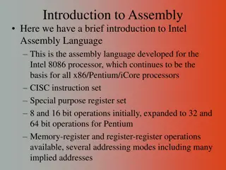
Understanding Assembly Language Programming
Assembly language provides a bridge between human-readable instructions and machine code, making it easier for programmers to interact with hardware. This content covers the basics of assembly language syntax, opcodes, operands, and labels, as well as the role of the assembler in converting human-readable code to machine instructions.

Download Presentation

Please find below an Image/Link to download the presentation.
The content on the website is provided AS IS for your information and personal use only. It may not be sold, licensed, or shared on other websites without obtaining consent from the author. Download presentation by click this link. If you encounter any issues during the download, it is possible that the publisher has removed the file from their server.
E N D
Presentation Transcript
CHAPTER 7 & 9.2 CHAPTER 7 & 9.2 ASSEMBLY LANGUAGE ASSEMBLY LANGUAGE Adapted from slides provided by McGraw-Hill Companies Inc., modified by professors at University of Wisconsin-Madison
Why machine language? + The closest language to H/W. Allows us to control exactly what the processor does. - Too tedious to write and debug. 0 s and 1 s make our head spin!
Assembly Language Human readable Machine language Instruction pneumonic instead of opcode Some added functionality Labels to refer to memory locations Assembler: A program which converts the human readable form to machine instructions.
Assembly language syntax Each line of an assembly program may be Instruction LC-3 instruction An assembler directive (pseudo-operation) A comment (Blank lines are ignored) (Whitespaces and case are ignored) (Comments are ignored)
Instruction LABEL OPCODE OPERANDS ; COMMENTS optional mandatory
LC-3 Opcodes Reserved symbols/names to represent the LC-3 instruction type Whatever we used to call them in Chapter 5! Example: ADD, BR, LD, STR,
Operands Registers: Rn where n is register number Numbers: decimal(#50) or hex (x32) Labels: Symbolic name for memory location
Multiple Operands Separate multiple operands by comma Same order as in the binary instruction For example: 0001 001 010 0 00 101 ADD R1, R2, R5 ADD R1 R2 R5
Labels Placed at the beginning of a line Symbolic name for the memory address corresponding to that line. For example: LOOP ADD R1, R1, #-1 BRp LOOP Used to replace PCOffset in LC-3 instructions (LD, ST, LDI, STI, BR, JSR)
Labels (restrictions) Can be any alpha-numeric string Can include underscore _ in PennSim Should start with an alphabet Unenforced in PennSim 1 - 20 characters long Cannot be any of the reserved symbols of LC-3 (like ADD, .ORIG, 19, xA3 etc.)
Comments Anything after the semicolon ; Ignored by the assembler. Can be used by the programmer to Document code Separate pieces of the program
Assembler directives Pseudo operations Not an instruction executed by the program, but used by the assembler Opcode with a dot .
Assembler directives Opcode Operand address Meaning starting address of program end of program allocate one word, initialize with value n allocate n words of storage .ORIG .END .FILL n n .BLKW n-character string allocate n+1 locations, initialize w/characters and null terminator .STRINGZ
Pseudo-Instructions Names for various TRAP codes so that you don t need to remember them! Code Equivalent Description Halt execution and print message to console. Print prompt on console, read (and echo) one character from keybd. Character stored in R0[7:0]. Write one character (in R0[7:0]) to console. HALT TRAP x25 IN TRAP x23 OUT TRAP x21 Read one character from keyboard. Character stored in R0[7:0]. Write null-terminated string to console. Address of string is in R0. GETC TRAP x20 PUTS TRAP x22
A full program ; ; Program to multiply a number by the constant 6 ; .ORIG x3050 LD R1, SIX LD R2, NUMBER AND R3, R3, #0 ; The inner loop ; AGAIN ADD R3, R3, R2 ADD R1, R1, #-1 BRp AGAIN ; HALT ; NUMBER .BLKW 1 SIX .FILL x0006 ; .END ; Clear R3. It will ; contain the product. ; R1 keeps track of ; the iteration.
Pseudo-code to Assembly R1 <- R2 + R3 ADD R1, R2, R3 R1 <- R1 AND 10 AND R1, R1, #10 OR AND R1, R1, xA
Pseudo-code to Assembly R5 = M[M[x3020]] (address x3020 has a label NUMBER ) LDI R5, NUMBER BR on Z or P to x3030 (address x3030 has a label LOOP ) BRzp LOOP
Pseudo-code to Assembly R6 = M[R2+5] LDR R6, R2, #5 BR unconditionally to x301E (address x301E has a label NEXT ) BRnzp NEXT OR BR NEXT
Pseudo-code to Assembly Write data x5000 to memory (add a label ADDR to that mem loc) ADDR .FILL x5000 Store a string Hi to memory (add a label STR to that mem loc) STR .STRINGZ Hi
Writing an Assembly Program Count the number of occurrences of a character in a string. [OR] Set the value of x4000 to the count of occurrences of a character, stored at x4001, in a null-terminated string, starting at x4002
Assembler Program which converts an assembly language program into machine code. In programming terms, converts your assembly language file (.asm/.txt) into an executable (.obj) file. We will use the inbuilt assembler in PennSim
Assembly process Two pass process
Assembly Process: 1st Pass Scan the program file and create a Symbol Table Symbol Table: A table which contains the addresses of all the labels in your assembly language program.
1st Pass: Steps 1. Find the .ORIG statement, which tells us the address of the first instruction. Initialize location counter (LC), which keeps track of the current instruction. 2. For each non-empty line in the program: If line contains a label, add label and LC to symbol table. Increment LC. Note: If statement is .BLKW or .STRINGZ, increment LC by the number of words allocated. 3. Stop when .END statement is reached. Note: A line that contains only a comment is considered an empty line.
1st Pass: Practice ; ; Program to multiply a number by the constant 6 ; .ORIG x3050 LD R1, SIX LD R2, NUMBER AND R3, R3, #0 ; The inner loop AGAIN ADD R3, R3, R2 ADD R1, R1, #-1 BRp AGAIN ; END HALT ; RAND .FILL x41FF GREET .STRINGZ 252! NUMBER .BLKW 2 SIX .FILL x0006 ; Clear R3. It will ; contain the product. ; R1 keeps track of ; the iteration. .END
1st Pass: Practice Symbol Address AGAIN x3053 END x3056 RAND x3057 GREET x3058 NUMBER x305D SIX x305F
Assembly Process: 2nd Pass Generate machine code for each line of assembly statement Use the symbol table to get the addresses of the labels, so as to calculate the PCOffset
Assembly Process: 2nd Pass Errors identified in this pass Improper number or type of arguments ex: NOT R1,#7 ADD R1,R2 ADD R3,R3,NUMBER Immediate argument too large ex: ADD R1,R2,#1023 Address (associated with label) more than specifiable by offset from instruction
2nd Pass: Practice For the previous example, generate machine code for instructions at address: x3050: x3055:
2nd Pass: Practice For the previous example, generate machine code for instructions at address: x3050: 0010 001 000001110 x3055: 0000 001 111111101
Issues Assembly done. Great! How to execute the code? How to write code in a team? Many people writing many assembly files? How to use vendor defined libraries?
Loading Process of copying an executable (.obj) into memory. We can load multiple .obj files, each starting at a desired address. User code: x3000 - xFDFF Careful! Do not overlap the object files
Linking Process of resolving symbols between independent object files Suppose we want to use a symbol (label) defined in a different .obj file some notation, such as .EXTERNAL, is used to tell assembler that a symbol is defined in another module linker will search symbol tables of other modules to resolve symbols and complete code generation before loading
Subroutines (Section 9.2) Very similar to functions in High Level Languages Arguments Return Value foo() { ... c = a + b d = bar(c, a) e = d + 3 ... } bar(x, y) { z = x * y return z } Callee/Called Function Caller Function
Subroutines A program fragment the performs a well defined task Invoked (or called) by a user program Returns control when the called program has finished
Arguments & Return Values Arguments The value(s) passed into a subroutine Return Values The value(s) passed out of a subroutine
Why subroutines? Reuse useful and debugged code, rather than redoing work Divide task among multiple programmers Use vendor supplied library of routines
How to call a subroutine? Use assembly instructions: JSR or JSRR Jumps to a location, like BR, but unconditionally Before jumping, copies (saves) PC into R7 Can use this saved PC to return to the caller program
JSR & JSRR Even though two assembly instructions, same OPCODE in binary Differ in bit 11 of the instruction Instruction JSR JSRR Bit 11 1 0 Target Address PC + PCOffset11 Base Register
JSR (PC-Relative) 15 14 13 12 11 10 9 8 7 6 5 4 3 2 1 0 0 1 0 0 1 PCoffset11
JSRR (Register) 15 14 13 12 11 10 9 8 7 6 5 4 3 2 1 0 0 1 0 0 0 0 0 Base Reg 0 0 0 0 0 0
JSR & JSRR What is the advantage of JSRR over JSR?
How to return to the caller? Using the RET assembly instruction Alias (pseudo-instruction) for JMP R7 15 14 13 12 11 10 9 8 7 6 5 4 3 2 1 0 JMP 1 1 0 0 0 0 0 Base Reg 0 0 0 0 0 0 Fix Base Register as R7 15 14 13 12 11 10 9 8 7 6 5 4 3 2 1 0 RET 1 1 0 0 0 0 0 1 1 1 0 0 0 0 0 0
Arguments and Return Values Normally registers are used to Pass arguments from caller to callee Return value from callee to caller Registers being used to pass arguments and return values should be explicitly stated when writing a subroutine
Example ; value is R0 is negated and returned ; Argument: R0 ; Return: R0 2sComp NOT R0, R0 ; flip bits ADD R0, R0, #1 ; add one RET ; return to caller Note: Call must be from within 1024 memory locations! ... ; need to compute R4 = R1 - R3 ADD JSR ADD ... R0, R3, #0 ; copy R3 to R0 2sComp ; negate R4, R1, R0 ; add to R1
Other Issues The caller and the callee use the same 8 General Purpose Registers (R0-R7) What if the callee modifies registers which are being used by the caller? Let us revisit our example and modify the subroutine:
Example R1 modified! ; value is R0 is negated and returned ; Argument: R0 ; Return: R0 2sComp NOT R0, R0 ; flip bits ADD R0, R0, #1 ; add one RET RET ; value is R0 is negated and returned ; Argument: R0 ; Return: R0 2sComp NOT R1, R0 ; flip bits ADD R0, R1, #1 ; add one ; return to caller ; return to caller Note: Call must be from within 1024 memory locations! ... R1 s value has changed! ; need to compute R4 = R1 - R3 ADD JSR ADD ... R0, R3, #0 ; copy R3 to R0 2sComp ; negate R4, R1, R0 ; add to R1
Two solutions! Caller-save [problem solved by the caller] Callee-save [problem solved by the callee]
Caller-save Caller knows which registers are modified by the callee Caller saves those registers before the call and restores them after the call Generally, modified registers are not known Solution: Save all registers
Example ; value is R0 is negated and returned ; Argument: R0 ; Return: R0 2sComp NOT R1, R0 ; flip bits ADD R0, R1, #1 ; add one RET ; return to caller ... ... ; need to compute R4 = R1 - R3 ADD JSR ADD ... LD ADD ... SAVE_R1 .BLKW 1 ; need to compute R4 = R1 - R3 ADD ST JSR R0, R3, #0 ; copy R3 to R0 2sComp ; negate R4, R1, R0 ; add to R1 2sComp ; negate R1, SAVE_R1 ; Restore R1 R4, R1, R0 ; add to R1 R0, R3, #0 ; copy R3 to R0 R1, SAVE_R1 ; Save R1


")


")


")
")