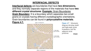
Advancing Electron Microscopy in Life Sciences through UEM Feasibility Demonstration
Demonstration project of the feasibility of a sub-nanometer, picosecond electron microscope for life sciences applications. The goal is to image biological cells with resolution below 200nm using a proof-of-concept system integrated with existing UED setup. The project builds on previous successes in electron beam focusing, aiming to enhance brightness and sharpness in electron diffraction. A positive review from a preliminary design committee indicates promising progress towards achieving the spatial resolution goal.

Download Presentation

Please find below an Image/Link to download the presentation.
The content on the website is provided AS IS for your information and personal use only. It may not be sold, licensed, or shared on other websites without obtaining consent from the author. Download presentation by click this link. If you encounter any issues during the download, it is possible that the publisher has removed the file from their server.
E N D
Presentation Transcript
LDRD for UEM (ID: 305506, UED) Demonstration of feasibility of sub-nm, picosecond electron microscope for the life sciences Xi Yang Representing UEM LDRD Team PI: Timur Shaftan/Sean McSweeney/Lewis Doom (NSLS-II), Yimei Zhu (CMPMSD), Qun Liu (Biology) LDRD 19-016 (approved and received) 22ndATF Users Meeting December 3 - 5, 2019 1
UEM LDRD participants NSLS-II D. Bergman, L. Doom, M Fulkerson, G. Ganetis, Y. Hidaka, B. Kosciuk, D. Padrazo, T. Shaftan, V. Smalyuk, C. Spataro, X. Yang, J. Rose, G. Wang, K. Wilson, L. H. Yu, etc. ATF M. Fedurin, M. Babzien, R. Malone, k. Kusche, C. Cullen, etc. CMPMSD J. Li, L. Wu, Y. Zhu, etc. ShanghaiTech University W. Wan 2
Goal of UEM LDRD This LDRD is to image biological cell with 10 m size with resolution <200nm. This effort is to design and test a proof-of-concept system, not an operational experimental instrument. The UEM system will be integrated into the current UED system with minimal interference. Expected Results: Phase I: Determine the UEM design and the required tolerances through accelerator physics studies. Phase II: Engineering design. Phase III: Equipment installed and proof-of-principle experiments carried out on a sample target at the UED setup 3 3
Design basis and foundation UEM LDRD is built on success of UED LDRD: Developed electromagnetic quadrupole focusing and corrector magnets and diagnostics for 3MeV beam Installation and commissioning Focused electron beam at high charge on sample to tens of micrometer Gain brightness and sharpness of diffraction pattern Design of compact ultrafast microscopes for single- and multi-shot imagining with MeV electrons. Ultramicroscopy. 194 143-153 (2018). Wan, W., Chen, F. & Zhu, Y. Projector 1 Projector 2 Objective Conventional UED configuration (with solenoid only focusing), UED with optimized quadrupoles Yang, X., et al. A compact tunable quadrupole lens for brighter and sharper ultra-fast electron diffraction imaging. Scientific Reports 9, 5115 (2019). 4 4
Preliminary Design Review Review committee members: D. Zakharov (BNL), M. Marko (Wadsworth), Q. Liu (BNL), M. Fedurin (BNL), E. Wang (BNL), P. Musumeci (UCLA) (Chair) The current effort represents fundamental research and is well aligned with DOE mission The committee commends BNL efforts in assembling a team with the right mixture of accelerator scientists and electron microscopists The efforts in making the system compatible with the existing UED research efforts are also to be highly praised. The committee generally agrees that the outlook to achieve the preliminary goal of 200 nm spatial resolution is positive and the goal is within reach of the current design effort, even considering the various deficiencies addressed later in this report. 5
Design principles of UEM beamline Novel approach: compact round imaging lens based on permanent quadrupole quintuplets The design resolution of the lens system: We conservatively chosen the resolution <200nm for the proof-of-principle experiment 1nm resolution is achievable with 10-5 electron beam energy spread 3-stage modular design simple design: the same objective and projector lenses Diagnostic system Enables stage-by-stage commissioning. Compatible with current UED System requirements are determined by accelerator physics analysis Magnet tolerances - fabrication, measurement and alignment. Electron beam parameters - charge, emittance and energy spread. Apertures and diagnostic flags - position, size, material and thickness. Beam-based characterization - spatial pointing and energy jitters of the electron beam 6 6 6
UEM beamline layout IMAGE 2 to DETECTOR 1.28 m IMAGE 1 to IMAGE 2 0.76 m SAMPLE to IMAGE 1 0.76 m Gun to SAMPLE - 1.39 m SAMPLE IMAGE 1 IMAGE 2 APER 4 1100 m APER 1 5 100 m Condenser lens APER 3 100 m Trim Q Solenoid APER 2 5 -180 m Resolution: dominated by electron beam qualities QF1 QF2 Trim Q Skew Q Trim Q Skew Q DETECTOR Gun APER are apertures. APER1 cuts dark current. APER2 controls aperture angle 0.1-3 mrad. C7 C1 C2 C3 C4 C6 C5 Projector lens #1 M2 = 108.2 f = 62 mm Objective lens M1 =10.4 f = 62 mm QD1 QD2 Projector lens #2 M3 = 2078.9 f = 62.2 mm Longitudinal Field Profile of the UEM lens Beamline lattice design is complete Quadrupoles are in production Design of the apertures is complete Beam flags will be reused, one more flag for the sample has been designed 7
Engineering implementation Modular magnet assemblies Objective, Projector 1 and Projector 2 are all the same Re-use as many other parts from UED LDRD Condenser and corrector magnets and power supplies Vacuum components Diagnostics: Flags, cameras, filter wheels Controls: electronics, switches, software Remote positioning sample, permanent magnets, apertures and flags Engineering design fast transition between UED and UEM modes Raspberry Pi Based Motion Control Corrector Condenser Quadrupole Quintuplet PM Quadrupoles 8 8
Studies on UED to assess feasibility of UEM Electron beam parameters: Charge at the detector Np n e = 0.4pC Np is the number of pixels of the detector (500*500) n is the estimated number of electrons per pixel (n = 10) Charge at the gun needs to be several times higher (1-5pC) due to electron-sample interaction ~10%. Beam size at the sample is ~10 m. Laser size on cathode ??,? 30 ?? Beam-based measurements: Shot-to-shot energy jitter is ~2 10-3. Spatial pointing jitters are ~10 rad. Energy spread ~4 10-3 at 2 pC Charge (pC) dE/E 0.0001 0.0100 0.05 5 References Yang, X., et al. A novel nondestructive diagnostic method for mega-electron-volt ultrafast electron diffraction. Scientific Reports 9, 17223 (2019). 9 9
Risk assessment Shot-to-shot energy jitter (~2 10-3) The energy jitter will limit the UEM performance in the low-charge accumulation mode. Energy spread (~10-2 for 4-5pC) Single-shot resolution of the UEM system will be limited by the energy spread at the required charge. Sample material how the biological sample scatters the electrons? Schedule is unknown How to mitigate risks? Apply NSLS-II LLRF system with better stability RF amplifier with better stability 10-4 Optimize laser parameters to improve electron beam quality 10 10 10
Plans Optimize system parameters at the nominal design energy. (2 weeks) Electron beam parameters (charge, bunch length, emittance and energy spread) as functions of machine parameters (laser size on cathode, laser intensity, gun phase and solenoid current). Set up online optimization (2 weeks) Imaging experiments with calibrated samples Golden and TaS2 single crystal samples. (1 week) Measure and optimize the resolution and magnification of sharp aperture edges. Understand effects of bunch charge, length, emittance and energy spread. (2 weeks) Imaging biological objects (~10um). (2 weeks). 11 11
Experiment Time Request CY2020 Time Request Capability Setup Hours Running Hours UED Facility 160 360 12 12
Special Equipment Requirements and Hazards User Sample and Setup Golden and TaS2 single crystal samples. Candidate biological samples: 1) Fatty acid synthase (Cryo-EM structure) http://www.rcsb.org/structure/6TA1 2) T4 baseplate-tail tube complex (the largest structure in PDB) (Cryo-EM structure) http://www.rcsb.org/structure/5IV5 3) Eukaryotic ribosome (Crystal structure) http://www.rcsb.org/structure/4V88 Special Equipment: UEM assembly Pump Laser Requirements: No Hazards & special installation requirements: Large installation (UEM assembly): Y Cryogens: Y Introducing new magnetic elements: Y Introducing new materials into the beam path: Y Any other foreseeable beam line modifications: N 13 13
Conclusion UEM physics design with <200nm resolution is complete Beam physics studies provide risks assessment Mitigation plans are under discussion Funded SBIR projects related to BNL UEM Design of a new superconducting gun Objective lens with high-gradient permanent magnet to reach sub-nm resolution 14
")