Machining Parameters and Calculations for Computer-Controlled Manufacturing
Understanding primary machining parameters such as cutting speed, feed rate, and depth of cut, along with operational aspects like turning, milling, and drilling. Exploring machining calculations including spindle speed, feed rate, and material removal rate for efficient computer-controlled manufacturing processes.

Uploaded on Oct 03, 2024 | 0 Views
Download Presentation

Please find below an Image/Link to download the presentation.
The content on the website is provided AS IS for your information and personal use only. It may not be sold, licensed, or shared on other websites without obtaining consent from the author. Download presentation by click this link. If you encounter any issues during the download, it is possible that the publisher has removed the file from their server.
E N D
Presentation Transcript
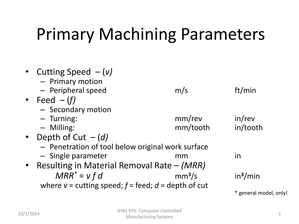
Primary Machining Parameters Cutting Speed (v) Primary motion Peripheral speed Feed (f) Secondary motion Turning: Milling: Depth of Cut (d) Penetration of tool below original work surface Single parameter Resulting in Material Removal Rate (MRR) MRR* = v f d where v = cutting speed; f = feed; d = depth of cut m/s ft/min mm/rev mm/tooth in/rev in/tooth mm in mm3/s in3/min * general model, only! IENG 475: Computer-Controlled Manufacturing Systems 10/3/2024 1
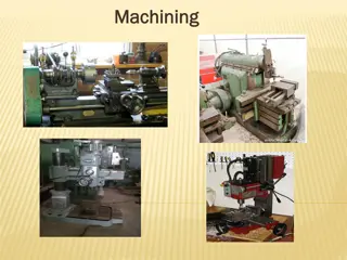
Machining Operations & Parameters Operation Type Turning: workpiece rotates single point cutting Speed Feed Depth of Cut Surface speed (periphery) of workpiece Parallel to the workpiece axis* (except parting/grooving) Tool penetration below original work surface Drilling: tool rotates single pass cutting Surface speed (periphery) of tool Parallel to the tool axis Tool penetration below original work surface (depth of hole) Milling: tool rotates multi-point cutting Surface speed (periphery) of tool Perpendicular to the tool axis Tool penetration below original work surface IENG 475: Computer-Controlled Manufacturing Systems 10/3/2024 2
Cut Types: Roughing & Finishing Number of Passes 1 + Cut Type Speed Feed Depth of Cut Roughing: removes large amounts to get close to shape Finishing: achieves final dimensions, tolerances, and finish Low High High 0.4 - 1.25 mm/ .015 - .050 in/ 2.5 - 20 mm .100 - .750 in 1 - 2 High Low Low 0.125 - 0.4 mm/ .005 - .015 in/ 0.75 - 2.0 mm .030 - .075 in IENG 475: Computer-Controlled Manufacturing Systems 10/3/2024 3
Machining Calculations: Turning k v Spindle Speed - N v = cutting speed Do = outer diameter Feed Rate - fr f = feed per rev (rpm) N = D k = 1000 mm/m for metric units -or- k = 12 in/ft for U.S. customary units o (mm/min -or- in/min) fr= N f D D Depth of Cut d Do = outer diameter Df = final diameter Machining Time - Tm L = length of cut (mm -or- in) = d o f 2 L (min) T = m f r 2 2 o ( D D ) f N (mm3/min -or- in3/min)* *This equation is the SDSM&T form! Mat l Removal Rate - MRR 4 = MRR f IENG 475: Computer-Controlled Manufacturing Systems 10/3/2024 4
Machining Calculations: Turning CAUTION! CAUTION! CAUTION! CAUTION! CAUTION! CAUTION! CAUTION! CAUTION! Spindle Speed - N v = cutting speed Do = outer diameter Feed Rate - fr f = feed per rev N = (rpm) v D o (mm/min -or- in/min) fr= N f Depth of Cut - d Do = outer diameter Df = final diameter Machining Time - Tm L = length of cut (mm -or- in) D D = d o f 2 L (min) T = m f r (mm3/min -or- in3/min)* Mat l Removal Rate - MRR MRR = v f d * This approximate equation assumes that f has units of mm or inches in accordance with Groover and Rufe (SME) texts. IENG 475: Computer-Controlled Manufacturing Systems 10/3/2024 5
Machining Calculations: Turning CAUTION! CAUTION! CAUTION! CAUTION! CAUTION! CAUTION! CAUTION! CAUTION! Spindle Speed - N v = cutting speed Do = outer diameter Feed Rate - fr f = feed per rev N = (rpm) v D o (mm/min -or- in/min) fr= N f Depth of Cut - d Do = outer diameter Df = final diameter Machining Time - Tm L = length of cut (mm -or- in) D D = d o f 2 L (min) T = m f r (mm3/min -or- in3/min)* Mat l Removal Rate - MRR = MRR v f d r * This approximate equation assumes that d is small compared to D0 in accordance with DeGarmo, et. al. texts. IENG 475: Computer-Controlled Manufacturing Systems 10/3/2024 6
Machining Calculations: Turning CAUTION! CAUTION! CAUTION! CAUTION! CAUTION! CAUTION! CAUTION! CAUTION! v Spindle Speed - N v = cutting speed Do = outer diameter Feed Rate - fr f = feed per rev N = (rpm) D o (mm/min -or- in/min) fr= N f D D Depth of Cut - d Do = outer diameter Df = final diameter Machining Time - Tm L = length of cut (mm -or- in) = d o f 2 L (min) T = m f r (mm3/min -or- in3/min)* In this equation: in accordance with Kalpakjian, et. al. texts. Mat l Removal Rate - MRR avg = MRR D d f N + D D o f = D avg 2 IENG 475: Computer-Controlled Manufacturing Systems 10/3/2024 7
Machining Calculations: Drilling Spindle Speed - N v = cutting speed D = tool diameter Feed Rate - fr f = feed per rev N = (rpm) v D (mm/min -or- in/min) fr= Nf ? = ??2 Machining Time - Tm Through Hole : t = thickness = tip angle (min) ) ( + t D tan 90 - 1 = T 2 2 m f r d Blind Hole : d = depth T = m f r ??? =??2fr (mm3/min -or- in3/min) ??? =??2Nf Mat l Removal Rate - MRR 4 Alternatively: 4 IENG 475: Computer-Controlled Manufacturing Systems 10/3/2024 8
Machining Calculations: Milling Spindle Speed - N v = cutting speed D = cutter diameter Feed Rate - fr f = feed per tooth nt = number of teeth Machining Time - Tm Slab Milling: L = length of cut d = depth of cut Face Milling: w = width of cut 2nd form is multi-pass N = (rpm) v D r= (mm/min -or- in/min) f N n f t L D (min) ( ) + d d - = T m f r ( ) + + L 2 w D w - L D = = T T -or- m m f f r r MRR = w d f (mm3/min -or- in3/min) Mat l Removal Rate - MRR r IENG 475: Computer-Controlled Manufacturing Systems 10/3/2024 9
Power and Energy Relationships Power requirements to perform machining can be computed from: Pc = Fc v where: Pc = cutting power; Fc = cutting force; and v = cutting speed Customary U.S. units for power are Horsepower (= 33000 ft-lb/min) N-m/s (W) ft-lb/min IENG 475: Computer-Controlled Manufacturing Systems 10/3/2024 10
Power and Energy Relationships The Gross machine power (Pg) available is: Pc = Pg E where E = mechanical efficiency of machine tool Typical E for machine tools = 80 - 90% Note: Alternate relationships for the same - P HP c c g= g= P HP E E IENG 475: Computer-Controlled Manufacturing Systems 10/3/2024 11
Unit Power in Machining Useful to convert power into power per unit volume rate of metal cut Called the unit power, Pu or unit horsepower, HPu P HP u= c or c u= P HP MRR MRR where MRR = material removal rate IENG 475: Computer-Controlled Manufacturing Systems 10/3/2024 12
Specific Energy in Machining Unit power (Pu) is also known as the specificenergy(U), or the power required to cut a unit volume of material: P P U u = = F = c c MRR t w o where t0 = un-deformed chip thickness; w = width of the chip; and Fc = cutting force Units for specific energy are typically N-m/mm3(same as J/mm3) or as in-lb/in3 Table on Materials page approximates specific energy for several materials based on estimated hardness IENG 475: Computer-Controlled Manufacturing Systems 10/3/2024 13