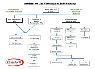
Overview of Manufacturing Systems: Types and Characteristics

Manufacturing systems are essential for transforming raw materials into finished products. This overview covers the types of manufacturing systems, such as job shops and flow shops, along with their characteristics, advantages, and disadvantages. It also introduces modern manufacturing systems like cellular manufacturing and flexible manufacturing. Understanding these systems is crucial for efficient production in various industries.

Download Presentation

Please find below an Image/Link to download the presentation.
The content on the website is provided AS IS for your information and personal use only. It may not be sold, licensed, or shared on other websites without obtaining consent from the author. Download presentation by click this link. If you encounter any issues during the download, it is possible that the publisher has removed the file from their server.
E N D
Presentation Transcript
1 CHAPTER 1 INTRODUCTION 1.1 MANUFACTURING SYSTEM Manufacturing, a branch of industry, is the application of tools and processes for the transformation of raw materials into finished products. The manufacturing sector is closely connected with engineering and industrial design. Some industries, such as semiconductor and steel manufactures use the term fabrication instead. Manufacturing includes all intermediate processes required for the production and integration of a product s components. The term manufacturing system refers to a collection or arrangement of operations and processes used to make a desired product or component. It includes the actual equipments for composing the processes and the arrangement of those processes. In a manufacturing system, if there is a change or disturbance in the system, the system should accommodate or adjust itself and continue to function efficiently. Normally the effect of disturbance must be counteracted by controllable inputs or the system itself. Figure 1.1 gives the general definition for any manufacturing system.
2 Disturbances Inputs Outputs Material Products A manufacturing system is Energy Information Demand A physical elements characterized by measurable parameters complex arrangement of Service to user Social politics Defects and scrap Information Measurable parameters Productionrate Work in process inventory Percentage of defects Percentage on time delivery Daily/weekly/monthly production volume Totalcost Physical elements Machines for processing Tooling Material handling equipment People Figure 1.1 General definitions for any manufacturing system 2. TYPES OFMANUFACTURING SYSTEMS The manufacturing systems differ in structure or physical arrangement. According to the physical arrangement, there are four kinds of classical manufacturing systems and two modern manufacturing systems that is rapidly gaining acceptance in industries. The classical systems are 1. Job shop 2. Flow shop 3. Project shop 4. Continuous process
3 The modern manufacturing systems are 1. Linked cell system (Cellular manufacturing system) 2. Flexible manufacturing system (FMS) 1.2.1 Job shops In a Job shop, varieties of products are manufactured in small lot sizes to a specific customer order. To perform a wide variety of manufacturing processes, general purpose production equipment is required. Workers must have relatively high skill levels to perform a range of different work arrangements. The production machines are grouped according to the general type of manufacturing processes as shown in Figure 1.2. The lathes are in one department, drill presses in another and so on. Each different part requiring its own sequence of operations can be routed through the various departments in the proper order. For this ROUTE SHEETS are used. The layout made for this purpose is called as functional or process layout. Figure 1.2 Functional or process layout
4 Advantages of process layouts Can handle a variety of processing requirements Not particularly vulnerable to equipment failures Equipment used is less costly Possible to use individual incentive plans Disadvantages of process layouts In-process inventory costs can be high Challenging routing and scheduling Equipment utilization rates are low Material handling is slow and inefficient Complexities often reduce span of supervision Special attention for each product or customer Accounting and purchasing are more involved Examples: Machine shops, foundries, press working shops, plastic industries. 1.2.2 Flow shops The flow shops have a product oriented layout composed mainly of flow lines. This system can have high production rates. The plant may be designed to produce the particular product or family, using Special purpose machines rather than general purpose equipments. The skill level of the laborer tends to be lower than in production job shop. When the volume of production becomes large, it is called mass production . The material flow is through a sequence of operations by
5 material handling devices. The time the item spends in each station or location is fixed and equal. The workstations are arranged in line according to the processing sequence needed as shown in Figure 1.3. Line 1 WS12 WS13 WS14 WS15 WS11 Raw Finished Materials Storage Materials Storage Line 2 WS22 WS23 WS21 Product A Product B WS = Work Station Figure 1.3 Product layout Advantages of product layout High rate of output Low unit cost Labor specialization Low material handling cost High utilization of labor and equipment Established routing and scheduling Routing accounting and purchasing Disadvantages of product layout Creates dull, repetitive jobs Poorly skilled workers may not maintain equipment or quality of output Fairly inflexible to changes in volume
6 Highly susceptible to shutdowns Needs preventive maintenance Individual incentive plans are impractical Example: Automated assembly line and Television manufacturing factory. 1.2.3 Project shop In this type, a product must remain in a fixed position or location because of its size and weight. The materials, machines and people in fabrication are brought to site. The layout is also called as fixed position layout. Figure 1.4 shows the project shop layout. Example: Locomotive manufacturing, large aircraft assembly and ship building Figure 1.4 Project shop layout
7 Advantages of project layout Minimum capital investment Continuity of operation Less total production cost. Offers greater flexibility Allows the change in production design. Permits a plant to elevate the skill of its operators Disadvantages of project layout Machines, tools and workers take more time to reach the fixed position. Highly skilled workers are required. Complicated jigs and fixtures (work holding device) may be required. 1.2.4 Continuous process In this continuous process, the product seems to flow physically. This system is sometimes called as flow production when referring to the manufacture of either complex single parts, such as a canning operation, or assembled products such as TVs. However, this is not a continuous process, but high volume flow lines. In continuous process, the products really do flow because they are liquids, gases, or powers. Figure 1.5 shows the continuous process layout. It is the most efficient but least flexible kind of manufacturing system. It usually has the leanest and simplest production system because this manufacturing
8 system is the easiest to control because it has the least work- in- progress (WIP). Examples: Oil refineries, chemical process plants and food processing industries Figure 1.5 Continuous process layout 1.2.5 Linked cell manufacturing system Cellular manufacturing (CM) is a hybrid system for linking the advantages of both job shops (flexibility in producing a wide variety of products) and flow lines (efficient flow and high production rate). A cellular manufacturing system (CMS) is composed of linked cells . Figure 1.6 shows the main structure of cellular manufacturing system. In cells, the workstations are arranged like a flow shop. The machines can be modified, retooled and regrouped for different product lines within the same family of parts. This system has some degree of automatic control for loading and unloading of raw materials and work pieces, changing of tools, transferring of work pieces and tools between workstations. Cells are classified as manned and unmanned cells. In manned cells multifunctional operators can move from machine
9 to machine and the materials can be moved by the operator. In the unmanned cells, an industrial robot is located centrally in the cell for material handling. Automated inspection and testing equipment can also be a part of this cell. Figure 1.6 Main structure of cellular manufacturing System Advantages of CMS The advantages derived from CMS in comparison with traditional manufacturing systems in terms of system performance have been discussed in Farrington (1998), Kannan (1999),Suresh (2000), Hug (2001) and Assad (2003). These benefits have been established through simulation studies, analytical studies, surveys, and actual implementations. They can be summarized as follows: Setup time is reduced: A manufacturing cell is designed to handle parts having similar shapes and relatively similar sizes. For this reason, many of the parts can employ the same or similar holding devices (fixtures). Generic fixtures for a part family can
10 be developed so that time required for changing fixtures and tools is decreased. Lot sizes are reduced: Once setup times are greatly reduced in CM, small lots are possible and economical. Small lots also provide smooth production flow. Work-in-process (WIP) and finished goods inventories are reduced: With smaller lot sizes and reduced setup times, the amount of WIP can be reduced. The WIP can be reduced by 50% when the setup time is cut to half. In addition to the reduced setup times and WIP inventory, finished goods inventory is reduced. Instead of make-to-stock systems with parts either being run at long, fixed intervals or random intervals, the parts can be produced either JIT in small lots or at fixed, short intervals. Material handling costs and time are reduced: In CM, each part is processed completely within a single cell (wherever possible). Thus, part travel time and distance between cells is minimal. A reduction in flow time is obtained: Reduced materials handling time and reduced setup time greatly reduce flow time. Tool requirements are reduced: Parts produced in a cell are of similar shape, size, and composition. Thus, they often have similar tooling requirements. A reduction in space required: Reductions in WIP, finished goods inventories, and lot sizes lead to less space required. Throughput times are reduced: In a job shop, parts are transferred between machines in batches. However, in CM each
11 part is transferred immediately to the next machine after it has been processed. Thus, the waiting time is reduced substantially. Product quality is improved: Since parts travel from one station to another as single unit, they are completely processed in a small area. The feedback is immediate and the process can be stopped when things go wrong. Better overall control of operations: In a job shop, parts may have to travel through the entire shop. Scheduling and material control are complicated. In CM, the manufacturing facility is broken down into manufacturing cells and each part travels with a single cell, resulting in easier scheduling and control. The basic differences between functional layout and cellular layout is depicted in Table 1.1 Table 1.1 Differences between functional layout and cellular layout Dimension Number of moves between departments Travel distances Travel paths Job waiting times Throughput time Amount of work in process Supervision difficulty Scheduling complexity Equipment utilization Functional Cellular many few longer variable greater higher shorter fixed shorter lower higher lower higher lower higher lower lower higher
12 1.2.6 Flexible manufacturing system A FMS integrates all major elements of manufacturing into a highly automated system. The flexibility of FMS is such that it can handle a variety of part configurations and produce them in any order. Figure 1.7 shows flexible manufacturing system. The basic elements of FMS are a) works station b) automated material handling and automated storage and retrieval systems c) control systems. Because of major capital investment; efficient machine utilization is essential. Consequently proper scheduling and process planning are crucial, that are complex in nature. Because of the flexibility in FMS, no setup time is wasted in switching between manufacturing operations; the system is capable of different operations in different orders and on different machines. Figure 1.7 Flexible manufacturing system Advantages: Parts can be produced randomly in batch sizes, as small as one, and at lower cost. The lead times required for product changes are shorter
13 Reduced WIP Labour and inventories are reduced Production is more reliable, because the system is self correcting and so product quality is uniform. Increased machine utilization Fewer machines required Reduced factory floor space Greater responsiveness to change 3. BASICS OF CELLULAR MANUFACTURING As this research is concerned about CM, the basic aspects of CM are discussed here: 1. Group technology Group technology (GT) is a manufacturing philosophy in which similar parts are identified and grouped together to take advantage of their similarities in manufacturing and design. The grouped parts are called part family . 2. Part family A Part family is a collection of parts that which has similarity in design attributes (such as geometrical shape and size) and manufacturing attributes (sequence of processing steps required to make the part). The parts within a family are different, but their similarities are close enough to merit their identification as member of part family. The problem of grouping parts in to families can be solved by the following three methods.
14 Visual inspection Classification and coding Production flow analysis (PFA) 3. Visual inspection The Visual inspection is the least sophisticated and least expensive method. It involves the classification of parts in to part families by looking at either the physical parts or their photographs and arranging them into similar groupings. This method is generally considered to be the least accurate of three. 4. Classification and coding Classification is a process in which items are separated into groups based on the existence or absence of characteristic attributes. Coding is the process of establishing symbols to be used for meaningful communication. The characteristic attributes are grouped as design attributes, (such as basic external shape, basic internal shape, length/diameter ratio, material type, major dimension, minor dimension) manufacturing attributes, (such as major process, minor operations, major dimensions, surface finish, machine tool, operation sequence, production time, batch size, fixture needed, cutting tools) as design and manufacturing are the two main functional areas. Before a coding scheme can be constructed, a survey of all component features must be completed and then code values can be
15 assigned to the features. The selection of relevant features depends on the application of coding scheme, based on design or manufacturing. The coding scheme consists of a sequence of numerical digits devised to identify the part s design and machining attributes. The following are the important coding systems: Opitz classification and system Multi class system CODE system DCLASS system KK3 system 1.3.5 Production flow analysis PFA is a method for identifying part families and associated grouping of machine tools. PFA was introduced by J.L.Burbidge. PFA is introduced to analyse the operation sequence and machine routing for the produced material in the given shop. It groups parts with identical or similar routing together. These groups can be used to form logical machine cells in a GT layout. Since PFA uses manufacturing data rather than design data, it can overcome two possible anomalies. Parts whose basic geometries are quite different may nevertheless require identical processing routings. Parts whose basic geometries are similar may require different process routings. However the disadvantage of using PFA is that it takes the route sheets the way they are, with no consideration given to routings such as optimal or consistent or even logical routings.
16 4. Implementation of CM CM is implemented in three stages: I. Cell formation: Grouping the parts into part families and machines into cells by the parts production process. II. Facility layout: Layout of cells within the shop floor (inter-cell layout) and layout of machines within each cells (intra-cell layout) Scheduling: III. Scheduling of jobs in each cells. 1.4.1 Types of cellular manufacturing layout Inter-cell layout: The facility layout in CMS involves the arrangement of cells within the floor space so as to minimize the inter-cell movement of the parts. Figure 1.8 shows the inter-cell layout. Figure 1.8 Inter-cell layout Intra-cell layout: The machine layout in CMS involves the arrangement of machines within the cells so as to minimize the intra-cell (within) movement of the parts. Figure 1.9 shows the intra-cell layout in which 12 machines are arranged in a cell.
17 Cell Figure 1.9 Intra-cell layout 2. Types of intra-cell layout According to arrangement of machines I. Single row layout: In this layout, different types of machines may be arranged in a single row as close as possible to the sequence of operations. The layout may be assuming several shapes such as linear, semi-circular or U-shaped. The benefits of single row layouts are small material handling time and cost, unidirectional flow, less delays, better control of operations and the ability to use conveyors. Figures 1.10, 1.11 and 1.12 show the linear single row, semi-circular and U-shaped layouts respectively. Figure 1.10 Linear single row layout
18 Figure 1.11 Semi-circular layout Figure 1.12 U-Shaped layout II. Multi-row layout: The machines are arranged in more than one row in this type of layout. The machines in each row interact with each other as well as with the machines in other rows. Figure 1.13 shows the arrangement of the machines in the multi row layout. Row 1 Row 2 Row 3 Figure 1.13 Multi-row layout
19 III. Loop layout: In this layout, the machines are arranged around an oval path and the movement of parts is usually unidirectional. The major advantage of the loop layout is the flexibility it provides in material handling. Figure 1.14 shows the loop layout. Figure 1.14 Loop layout According to environment I.Machine layout under static environment: In this environment, the layout does not change over the planning horizon since there is no change in the material flow. II.Machine layout under dynamic environment: In this environment, the layout requires change due to the following reasons: Change in the design of existing product Change in the processing sequence of existing product Fluctuation in demand Changes in number of products in the product mix To meet out the above changes, modular equipment, general- purpose production equipment, material handling devices, etc., are used in the machine layout under dynamic environment.
20 When GT is applied to a manufacturing system, the following benefits can be achieved. Engineering design Reduction in new parts design Reduction in the number of drawings through standardization Reduction of drafting effort in new shop drawings Reduction of number of similar parts, easy retrieval of similar functional parts, and identification of substitute parts Layout planning Reduction in production floor space required Reduced material-handling effort Equipment, tools, jigs, and fixtures Standardization of equipment Reduced number of tools, pallets, jigs, and fixtures Significant reduction in costs of releasing new parts Process planning Reduction in setup time and production time Improved machine loading and shortened production cycles Reduction in number of machining operations and numerical control (NC) programming time
21 Production control Reduced work-in-process inventory Easy identification of bottlenecks Improved material flow and reduced warehousing cost Faster response to schedule changes Improved usage of fixtures, pallets, tools, material handling, and manufacturing equipment Quality control Reduction in number of defects leading to reduced inspection effort Reduced scrap generation Better output quality Purchasing Coding of purchased parts leading to standardized rules for purchasing Reduced number of parts and raw materials Economies in purchasing because of accurate knowledge of raw material requirements Simplified vendor evaluation procedures leading to JIT purchasing
22 Customer satisfaction Accurate and faster cost estimates Efficient spare parts management, leading to better customer services Employee satisfaction The workers in a cell observe the parts from raw material state to the finished part state. They visualize their contribution to the firm, and are more satisfied. Work part quality is more easily traced in GT, and so the workers are more responsible for the quality of work they accomplish 5. PROBLEM STATEMENT Although the benefits of CM are substantial, the facility layout problem in CM has not captured researcher s attention as much as cell formation. The layout problem however plays an important role in the design of CM. The motivation of this research is to develop a model to solve machine assignment problems under static and dynamic environments. 6. RESEARCH OBJECTIVES Develop a model to solve the problem of machine assignment within a cell of CMS under static and dynamic environments with the objective of minimize the total cost, which is the sum of material handling cost, relocation cost and production loss cost.
23 7. RESEARCH APPROACH To achieve the development of the new model, the research approach consists of the following steps: 1. Formulate a mathematical model for static and dynamic environment. 2. Genetic Algorithm (GA) is proposed to solve the problem. 3. Numerical illustration and case study are used for validating the developed model. 4. Solve the numerical illustration and case study via the proposed GAand analyze results. 5. The performance GA is compare with the performance of other heuristics and optimal solution. 6. Draw conclusions and discuss the directions for future work. 8. OUTLINE OF THESIS The remainder of this dissertation is organized as follows. Chapter 2 reviews the literature, which helps in defining and solving the machine assignment problems in CMS and GA. Chapter 3 presents about the GA and the proposed GA to solve problems under static and dynamic environment. In chapter 4 defines the problem. Chapter 5 discusses machine assignment in single row and multi row layout under static environment. Chapter 6 explains the machine assignment in single row and multi row layout under dynamic environment with numerical examples and case study. Finally, Chapter 7 presents the conclusion, contributions, and future research.