JCB WORKMAX 800D UTV Service Repair Manual Instant Download
Please open the website below to get the complete manualnn//

Download Presentation

Please find below an Image/Link to download the presentation.
The content on the website is provided AS IS for your information and personal use only. It may not be sold, licensed, or shared on other websites without obtaining consent from the author. Download presentation by click this link. If you encounter any issues during the download, it is possible that the publisher has removed the file from their server.
E N D
Presentation Transcript
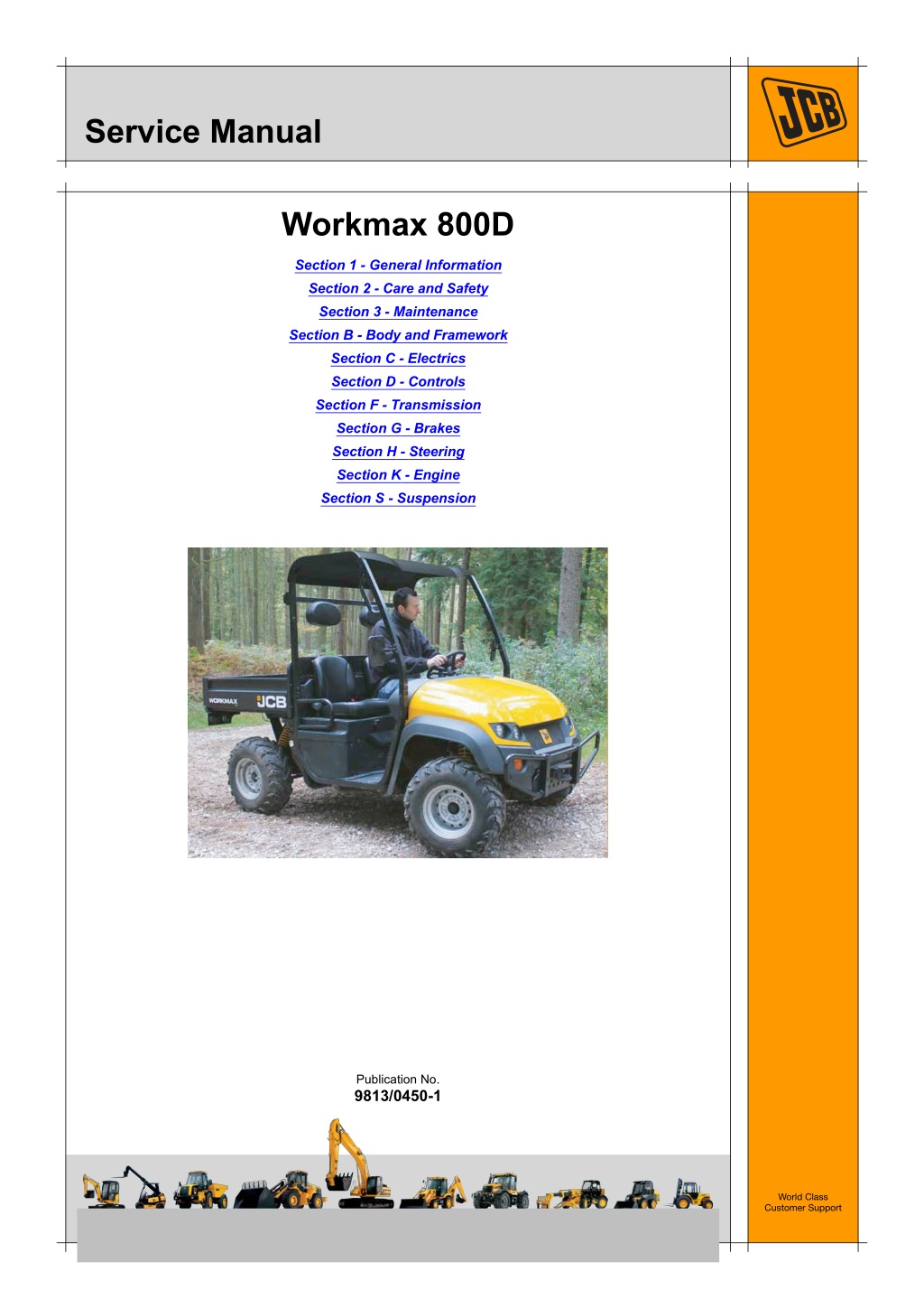
Service Manual Workmax 800D Section 1 - General Information Section 2 - Care and Safety Section 3 - Maintenance Section B - Body and Framework Section C - Electrics Section D - Controls Section F - Transmission Section G - Brakes Section H - Steering Section K - Engine Section S - Suspension Publication No. 9813/0450-1 World Class Customer Support Copyright 2004 JCB SERVICE. All rights reserved. No part of this publication may be reproduced, stored in a retrieval system, or transmitted in any form or by any other means, electronic, mechanical, photocopying or otherwise, without prior permission from JCB SERVICE. Issued by JCB Technical Publications, JCB Aftermarket Training, Woodseat, Rocester, Staffordshire, ST14 5BW, England. Tel +44 1889 591300 Fax +44 1889 591400
Section 1 - General Information Notes: 1-0 1-0 9813/0450-1
Section 1 - General Information Contents Introduction About this Manual ...................................................................................... 1-1 Machine Model and Serial Number .......................................................1-1 Using this Manual ..................................................................................1-1 Left Side, Right Side ..............................................................................1-1 Cab/Canopy ..........................................................................................1-1 Cross References ..................................................................................1-1 Machine Description .................................................................................. 1-2 The JCB Workmax 800D .......................................................................1-2 Intended Use .........................................................................................1-2 Component Location .............................................................................1-2 Identifying Your Machine ........................................................................... 1-3 Machine Identification Plate ..................................................................1-3 Typical Product Identification Number Data Plate .................................1-4 Component Identification Plates ............................................................1-4 Page No. Fastener Torque Chart Zinc Plated Fasteners and Dacromet Fasteners ....................................... 1-7 Introduction ............................................................................................1-7 Bolts and Screws ...................................................................................1-7 Service Tools Numerical List .......................................................................................... 1-11 Consumables Sealing and Retaining Compounds ......................................................... 1-13 1-i 1-i
https://www.ebooklibonline.com Hello dear friend! Thank you very much for reading. Enter the link into your browser. The full manual is available for immediate download. https://www.ebooklibonline.com
Section 1 - General Information Contents Page No. 1-ii 1-ii
Section 1 - General Information Introduction About this Manual Machine Model and Serial Number Left Side, Right Side This manual provides information for the following model(s) in the JCB machine range: In this manual, 'left' A and 'right' B mean your left and right when you are seated correctly in the machine. Cab/Canopy Workmax 800D SN 1629000 to 1632999. T1-003_2 Using this Manual This manual frequently makes references to the cab. For instance, 'do not operate the machine without a manual in the cab'. It should be noted that these statements also apply to canopy build machines. T1-044 This manual is arranged to give you a good understanding of the machine and its safe operation. It also contains maintenance information and specification data. Read this manual from front to back before using the machine for the first time. Particular attention must be given to all the safety aspects of operating and maintaining the machine. Cross References T1-004_2 In this publication, page cross references are made by presenting the subject title printed in bold, italic and underlined. It is preceeded by the 'go to' symbol. The number of the page upon which the subject begins, is indicated within the brackets. For example: K References ( T T 1-1). If there is anything you are not sure about, ask your JCB distributor or employer. Do not guess, you or others could be killed or seriously injured. K Cross General warnings in this chapter are repeated throughout the book, as well as specific warnings. Read all the safety statements regularly, so you do not forget them. Remember that the best operators are the safest operators. The illustrations in this manual are for guidance only. Where the machines differ, the text and or the illustration will specify. This manual contains original instructions, verified by the manufacturer (or their authorised representative). The manufacturer's policy is one of continuous improvement. The right to change the specification of the machine without notice is reserved. No responsibility will be accepted for discrepancies which may occur between specifications of the machine and the descriptions contained in this publication. All optional equipment included in this manual may not be available in all territories. 1-1 1-1 9813/0450-1
Section 1 - General Information Introduction Machine Description Machine Description The JCB Workmax 800D Component Location The JCB Workmax 800D is a utility vehicle fitted with a loadbay. The vehicle has a diesel engine which drives through a Continuously Variable Transmission (CVT). Note: The illustration(s) show a typical machine model; your machine may look different from the model shown. 1 Front access panel The driven axles have differentials, the rear differential incorporates a differential lock. The brakes are hydraulically operated, with discs and callipers on all four wheels. 2 Roll Over Protection Structure (ROPS) 3 Loadbay Intended Use 4 Engine (below the loadbay) 5 Gearbox (below the loadbay) The machine is intended to be used under normal conditions for the applications described in this manual. If the machine is used for other purposes or in dangerous environments, for example in a flammable atmosphere or in areas with dust containing asbestos, special safety regulations must be followed and the machine must be equipped for use in these environments. 6 Battery (below the loadbay) C100390-B1 Fig 1. C100790-B5 Fig 2. 1-2 1-2 9813/0450-1
Section 1 - General Information Introduction Identifying Your Machine Identifying Your Machine Machine Identification Plate If the engine is replaced by a new one, the serial number on the identification plate will be wrong. Either get a replacement identification plate from your JCB Dealer or simply remove the old number. This will prevent the wrong unit number being quoted when replacement parts are ordered. Your machine has an identification plate mounted as shown. The Product Identification Number (PIN), weight, engine power, year of manufacture and serial number of the machine are shown on the plate. The machine and engine serial numbers can help identify exactly the type of equipment you have. Note: The machine model and build specification is indicated by the PIN. Refer to Typical Product Identification Number (PIN). JCB COMPACT PRODUCTS LIMITED HAREWOOD ESTATE, LEEK ROAD, CHEADLE, STOKE ON TRENT, UNITED KINGDOM, ST10 2JU. WEIGHT kg, ISO 6016 ENGINE POWER kW @ RPM ISO 14396 YEAR OF MANUFACTURE Product Identification Number, PIN, ISO 10261 TYPE 817/18435 Fig 3. Position of Identification Plate 1-3 1-3 9813/0450-1
Section 1 - General Information Introduction Identifying Your Machine Typical Product Identification Number Data Plate Component Identification Plates Typical Engine Identification Plate Code A B C D E Engine Model 3TNM68A Example JCB B E 1629000 A - World Manufacturer Identification (3 Digits) B - Machine Model (5 Digits) C - Randomly Generated Check Letter (1 Digit) D - Year of Manufacture (1 Digit) E - Machine Serial Number (7 Digits) THIS ENGINE COMPLIES WITH USA EPA AND CALIFORNIA REGULATIONS FOR 2009 M.Y. AND STATIONARY/OFF ROAD DIESEL ENGINES 9YDXLO. 78V3N 3TN M68A 0.784 EM Each machine has a unique serial number. A = 2010 B = 2011 C100740 C = 2012 Fig 4. The plate is attached to the engine at G. K K Fig 5. ( T T 1-4) C100750 Fig 5. In addition to the plate at G, the engine model and serial number are stamped on flat pads on the left side of the crankcase 1-4 1-4 9813/0450-1
Section 1 - General Information Introduction Identifying Your Machine ROPS Data Plate !MWARNING The vehicle may be fitted with a Roll Over Protection Structure (ROPS). You could be killed or seriously injured if you operate the machine with a damaged or missing ROPS. If the ROPS has been in an accident, do not use the machine until the structure has been renewed. Modifications and repairs that are not approved by the manufacturer may be dangerous and will invalidate the ROPS certification. 13-1-1-27_1 The machine is built to the ROPS standard and has a data plateattached to the frame. For an example of the ROPS data plate, see illustration. K K Fig 6. ( T T 1-5) C100890 Fig 6. 1-5 1-5 9813/0450-1
Section 1 - General Information Introduction Identifying Your Machine Page left intentionally blank 1-6 1-6 9813/0450-1
Section 1 - General Information Fastener Torque Chart Zinc Plated Fasteners and Dacromet Fasteners Fastener Torque Chart Zinc Plated Fasteners and Dacromet Fasteners T11-002 Introduction Bolts and Screws Some external fasteners on JCB machines are manufactured using an improved type of corrosion resistant finish. This type of finish is called Dacromet and replaces the original Zinc and Yellow Plating used on earlier machines. Use the following torque setting tables only where no torque setting is specified in the text. Note: Dacromet fasteners are lubricated as part of the plating process, do not lubricate. The two types of fasteners can be readily identified by colour and part number suffix. K ( T T 1-7). Torque settings are given for the following conditions: K Table 1. Fastener Types Condition 1 Table 1. Fastener Types Colour Un-lubricated fasteners Zinc fasteners Yellow plated fasteners Fastener Type Part No. Suffix Zinc and Yellow Golden finish 'Z' (e.g. 1315/3712Z) Condition 2 Dacromet Mottled silver finish 'D' (e.g. 1315/3712D) Zinc flake (Dacromet) fasteners Lubricated zinc and yellow plated fasteners Where there is a natural lubrication. For example, cast iron components Note: As the Dacromet fasteners have a lower torque setting than the Zinc and Yellow fasteners, the torque figures used must be relevant to the type of fastener. Note: A Dacromet bolt should not be used in conjunction with a Zinc or Yellow plated nut, as this could change the torque characteristics of the torque setting further. For the same reason, a Dacromet nut should not be used with a Zinc or Yellow plated bolt. Verbus Ripp Bolts Note: All bolts used on JCB machines are high tensile and must not be replaced by bolts of a lesser tensile specification. Fig 1. Note: Dacromet bolts, due to their high corrosion resistance are used in areas where rust could occur. Dacromet bolts are only used for external applications. They are not used in applications such as gearbox or engine joint seams or internal applications. Torque settings for these bolts are determined by the application. Refer to the relevant procedure for the required settings. 1-7 1-7 9813/0450-1
Section 1 - General Information Fastener Torque Chart Zinc Plated Fasteners and Dacromet Fasteners Table 2. Torque Settings - UNF Grade 'S' Fasteners Hexagon (A/F) Bolt Size Condition 1 Condition 2 in. mm in. Nm kgf m lbf ft Nm kgf m lbf ft 1/4 6.3 7/16 11.2 1.1 8.3 10.0 1.0 7.4 5/16 7.9 1/2 22.3 2.3 16.4 20.0 2.0 14.7 3/8 9.5 9/16 40.0 4.1 29.5 36.0 3.7 26.5 7/16 11.1 5/8 64.0 6.5 47.2 57.0 5.8 42.0 1/2 12.7 3/4 98.00 10.0 72.3 88.0 9.0 64.9 9/16 14.3 13/16 140.0 14.3 103.2 126.0 12.8 92.9 5/8 15.9 15/16 196.0 20.0 144.6 177.0 18.0 130.5 3/4 19.0 1 1/8 343.0 35.0 253.0 309.0 31.5 227.9 7/8 22.2 1 15/16 547.0 55.8 403.4 492.0 50.2 362.9 1 25.4 1 1/2 814.0 83.0 600.4 732.0 74.6 539.9 1 1/8 31.7 1 7/8 1181.0 120.4 871.1 1063.0 108.4 784.0 1 1/4 38.1 2 1/4 1646.0 167.8 1214.0 1481.0 151.0 1092.3 Table 3. Torque Settings - Metric Grade 8.8 Fasteners Hexagon (A/F) Bolt Size Condition 1 Condition 2 ISO Metric Thread mm mm Nm kgf m lbf ft Nm kgf m lbf ft M5 5 8 5.8 0.6 4.3 5.2 0.5 3.8 M6 6 10 9.9 1.0 7.3 9.0 0.9 6.6 M8 8 13 24.0 2.4 17.7 22.0 2.2 16.2 M10 10 17 47.0 4.8 34.7 43.0 4.4 31.7 M12 12 19 83.0 8.5 61.2 74.0 7.5 54.6 M16 16 24 205.0 20.9 151.2 184.0 18.8 135.7 M20 20 30 400.0 40.8 295.0 360.0 36.7 265.5 M24 24 36 690.0 70.4 508.9 621.0 63.3 458.0 M30 30 46 1372.0 139.9 1011.9 1235.0 125.9 910.9 M36 36 55 2399.0 244.6 1769.4 2159.0 220.0 1592.4 1-8 1-8 9813/0450-1
Section 1 - General Information Fastener Torque Chart Zinc Plated Fasteners and Dacromet Fasteners Table 4. Metric Grade 10.9 Fasteners Hexagon (A/F) Bolt Size Condition 1 Condition 2 ISO Metric Thread mm mm Nm kgf m lbf ft Nm kgf m lbf ft M5 5 8 8.1 0.8 6.0 7.3 0.7 5.4 M6 6 10 13.9 1.4 10.2 12.5 1.3 9.2 M8 8 13 34.0 3.5 25.0 30.0 3.0 22.1 M10 10 17 67.0 6.8 49.4 60.0 6.1 44.2 M12 12 19 116.0 11.8 85.5 104.0 10.6 76.7 M16 16 24 288.0 29.4 212.4 259.0 26.4 191.0 M20 20 30 562.0 57.3 414.5 506.0 51.6 373.2 M24 24 36 971.0 99.0 716.9 874.0 89.1 644.6 M30 30 46 1930.0 196.8 1423.5 1737.0 177.1 1281.1 M36 36 55 3374.0 344.0 2488.5 3036.0 309.6 2239.2 Table 5. Metric Grade 12.9 Fasteners Hexagon (A/F) Bolt Size Condition 1 Condition 2 ISO Metric Thread mm mm Nm kgf m lbf ft Nm kgf m lbf ft M5 5 8 9.8 1.0 7.2 8.8 0.9 6.5 M6 6 10 16.6 1.7 12.2 15.0 1.5 11.1 M8 8 13 40.0 4.1 29.5 36.0 3.7 26.5 M10 10 17 80.0 8.1 59.0 72.0 7.3 53.1 M12 12 19 139.0 14.2 102.5 125.0 12.7 92.2 M16 16 24 345.0 35.2 254.4 311.0 31.7 229.4 M20 20 30 674.0 68.7 497.1 607.0 61.9 447.7 M24 24 36 1165.0 118.8 859.2 1048.0 106.9 773.0 M30 30 46 2316.0 236.2 1708.2 2084.0 212.5 1537.1 M36 36 55 4049.0 412.9 2986.4 3644.0 371.6 2687.7 1-9 1-9 9813/0450-1
Section 1 - General Information Fastener Torque Chart Zinc Plated Fasteners and Dacromet Fasteners Table 6. Torque Settings - Rivet Nut Bolts/Screws Bolt Size ISO Metric Thread mm Nm kgf m lbf ft M3 3 1.2 0.1 0.9 M4 4 3.0 0.3 2.0 M5 5 6.0 0.6 4.5 M6 6 10.0 1.0 7.5 M8 8 24.0 2.5 18.0 M10 10 48.0 4.9 35.5 M12 12 82.0 8.4 60.5 Table 7. Torque Settings - Internal Hexagon Headed Cap Screws (Zinc) Bolt Size ISO Metric Thread Nm kgf m lbf ft M3 2.0 0.2 1.5 M4 6.0 0.6 4.5 M5 11.0 1.1 8.0 M6 19.0 1.9 14.0 M8 46.0 4.7 34.0 M10 91.0 9.3 67.0 M12 159.0 16.2 117.0 M16 395.0 40.0 292.0 M18 550.0 56.0 406.0 M20 770.0 79.0 568.0 M24 1332.0 136.0 983.0 1-10 1-10 9813/0450-1
Section 1 - General Information Service Tools Numerical List The tools listed in the table are special tools required for carrying out the procedures described in this manual. These tools are available from JCB Service. details of all tools, including the content of kits and sets, see the relevant section in this manual. Note: Tools other than those listed will be required. It is expected that such general tools will be available in any well equipped workshop or be available locally from any good tool supplier. Some tools are available as kits or sets, the part numbers for parts within such kits or sets are not listed here. For full Part Number Description Tool Detail Reference - see Section: - AVO Test Kit - see tool detail reference for content C - Electrical Repair Kit - see tool detail reference for content C 993/85700 Battery Tester C 1-11 1-11 9813/0450-1
Section 1 - General Information Service Tools Numerical List Page left intentionally blank 1-12 1-12 9813/0450-1
Section 1 - General Information Consumables Sealing and Retaining Compounds Consumables Sealing and Retaining Compounds T11-001_3 Table 1. Type Description Part No. Quantity JCB Multi-Gasket A medium strength sealant suitable for all sizes of gasket flanges, and for hydraulic fittings of 25-65 mm diameter. 4102/1212 50 ml JCB High Strength Threadlocker A high strength locking fluid for use with threaded components. Gasketing for all sizes of flange where the strength of the joint is important. 4102/0551 50 ml JCB Retainer (High Strength) For all retaining parts which are unlikely to be dismantled. 4101/0651 50 ml JCB Threadlocker and Sealer A medium strength locking fluid for sealing and retaining nuts, bolts, and screws up to 50 mm diameter, and for hydraulic fittings up to 25 mm diameter. 4101/0250 10 ml 4101/0251 50 ml JCB Threadlocker and Sealer (High Strength) A high strength locking fluid for sealing and retaining nuts, bolts, and screws up to 50 mm diameter, and for hydraulic fittings up to 25 mm diameter. 4101/0550 10 ml 4101/0552 200 ml JCB Threadseal A medium strength thread sealing compound. 4102/1951 50 ml JCB Activator A cleaning primer which speeds the curing rate of anaerobic products. 4104/0251 200 ml (Aerosol) 4104/0253 1 ltr (Bottle) JCB Cleaner/Degreaser For degreasing components prior to use of anaerobic adhesives and sealants. 4104/1557 400 ml (Aerosol) Direct Glazing Kit For one pane of glass; comprises of: 993/55700 1 x Ultra Fast Adhesive (310 ml) 1 x Active Wipe 205 (30 ml) 1 x Black Primer 206J (30 ml) plus applicator nozzle etc. Ultra Fast Adhesive For direct glazing. 4103/2109 310 ml Active Wipe 205 For direct glazing. 4104/1203 250 ml Black Primer 206J For direct glazing. 4201/4906 30 ml Clear Silicone Sealant To seal butt jointed glass. 4102/0901 Plastic to Metal Bonder To seal plastic to metal joints. 4103/0956 50 g Black Polyurethane Sealant To finish exposed edges of laminated glass. 4102/2309 310 ml 1-13 1-13 9813/0450-1
Section 1 - General Information Consumables Sealing and Retaining Compounds Page left intentionally blank 1-14 1-14 9813/0450-1
Section 2 - Care and Safety Notes: 2-0 2-0 9813/0450-1
Section 2 - Care and Safety Contents Safety Notices Important Information ................................................................................ 2-1 The Operator Manual ............................................................................2-1 Safety Warnings ....................................................................................2-1 Safety Check List ....................................................................................... 2-2 Safety - Yours and Others .....................................................................2-2 General Safety ......................................................................................2-2 Operating Safety ...................................................................................2-4 Maintenance Safety ...............................................................................2-8 Safety Labels ........................................................................................... 2-12 Introduction ..........................................................................................2-12 Safety Label Identification ...................................................................2-13 Page No. 2-i 2-i
Section 2 - Care and Safety Contents Page No. 2-ii 2-ii
Section 2 - Care and Safety Safety Notices Important Information T1-042 The Operator Manual Safety Warnings !MWARNING This safety alert system identifies important safety messages in this manual. When you see this symbol, be alert, your safety is involved, carefuly read the message that follows, and inform other operators. You and others can be killed or seriously injured if you operate or maintain the machine without first studying the Operator Manual. You must understand and follow the instructions in the Operator Manual. If you do not understand anything, ask your employer or JCB dealer to explain it. In this publication and on the machine, there are safety notices. Each notice starts with a signal word. The signal word meanings are given below. INT-1-4-2 Do not operate the machine without an Operator Manual, or if there is anything on the machine you do not understand. !MDANGER Denotes an extreme hazard exists. If proper precautions are not taken, it is highly probable that the operator (or others) could be killed or seriously injured. Treat the Operator Manual as part of the machine. Keep it clean and in good condition. Replace the Operator Manual immediately if it is lost, damaged or becomes unreadable. INT-1-2-1 !MWARNING Denotes a hazard exists. If proper precautions are not taken, the operator (or others) could be killed or seriously injured. INT-1-2-2 !MCAUTION Denotes a reminder of safety practices. Failure to follow these safety practices could result in injury to the operator (or others) and possible damage to the machine. INT-1-2-3 2-1 2-1 9813/0450-1
Section 2 - Care and Safety Safety Notices Safety Check List Safety Check List Safety - Yours and Others General Safety INT-1-3-1_3 T1-043 !MWARNING All machinery can be hazardous. When a machine is correctly operated and properly maintained, it is a safe machine to work with. But when it is carelessly operated or poorly maintained it can become a danger to you (the operator) and others. To operate the machine safely you must know the machine and have the skill to use it. You must abide by all relevant laws, health and safety regulations that apply to the country you are operating in. The Operator Manual instructs you on the machine, its controls and its safe operation; it is not a training manual. If you are a new operator, get yourself trained in the skills of using a machine before trying to work with it. If you don't, you will not do your job well, and you will be a danger to yourself and others. In this manual and on the machine you will find warning messages. Read and understand them. They tell you of potential hazards and how to avoid them. If you do not fully understand the warning messages, ask your employer or JCB distributor to explain them. But safety is not just a matter of responding to the warnings. All the time you are working on or with the machine you must be thinking what hazards there might be and how to avoid them. INT-1-4-1 !MWARNING Care and Alertness Do not work with the machine until you are sure that you can control it. All the time you are working with or on the machine, take care and stay alert. Always be careful. Always be alert for hazards. Do not start any job until you are sure that you and those around you will be safe. INT-1-3-5 !MWARNING If you are unsure of anything, about the machine or the job, ask someone who knows. Do not assume anything. Clothing You can be injured if you do not wear the proper clothing. Loose clothing can get caught in the machinery. Wear protective clothing to suit the job. Examples of protective clothing are: a hard hat, safety shoes, safety glasses, a well fitting overall, ear- protectors and industrial gloves. Keep cuffs fastened. Do not wear a necktie or scarf. Keep long hair restrained. Remove rings, watches and personal jewellery. Remember BE CAREFUL BE ALERT BE SAFE INT-1-3-6_2 !MWARNING Alcohol and Drugs It is extremely dangerous to operate machinery when under the influence of alcohol or drugs. Do not consume alcoholic drinks or take drugs before or while operating the machine or attachments. Be aware of medicines which can cause drowsiness. INT-1-3-9_2 2-2 2-2 9813/0450-1
Section 2 - Care and Safety Safety Notices Safety Check List !MWARNING !MDANGER Feeling Unwell Lightning Do not attempt to operate the machine if you are feeling unwell. By doing so you could be a danger to yourself and those you work with. Lightning can kill you. Do not use the machine if there is lightning in your area. 5-1-1-2 8-1-2-4 !MWARNING !MWARNING Machine Modifications Mobile Phones This machine is manufactured in compliance with legislative and other requirements. It should not be altered in any way which could affect or invalidate any of these requirements. For advice consult your JCB Distributor. Switch off your mobile phone before entering an area with a potentially explosive atmosphere. Sparks in such an area could cause an explosion or fire resulting in death or serious injury. INT-1-3-10_2 Switch off and do not use your mobile phone when refuelling the machine. INT-3-3-9 !MWARNING Lifting Equipment You can be injured if you use incorrect or faulty lifting equipment. You must identify the weight of the item to be lifted then choose lifting equipment that is strong enough and suitable for the job. Make sure that lifting equipment is in good condition and complies with all local regulations. INT-1-3-7_2 !MWARNING Raised Equipment Never walk or work under raised equipment unless it is supported by a mechanical device. Equipment which is supported only by a hydraulic device can drop and injure you if the hydraulic system fails or if the control is operated (even with the engine stopped). Make sure that no-one goes near the machine while you install or remove the mechanical device. 13-2-3-7_3 !MWARNING Raised Machine NEVER position yourself or any part of your body under a raised machine which is not properly supported. If the machine moves unexpectedly you could become trapped and suffer serious injury or be killed. INT-3-3-7_1 2-3 2-3 9813/0450-1
Section 2 - Care and Safety Safety Notices Safety Check List !MWARNING Operating Safety Work Sites !MWARNING Work sites can be hazardous. Inspect the site before working on it. You could be killed or injured if the ground gives way under your machine or if piled material collapses onto it. Check for potholes and hidden debris, logs, ironwork etc. Any of these could cause you to lose control of your machine. Check for utilities such as electric cables (overhead and underground), gas and water pipes etc. Mark the positions of the underground cables and pipes. Make sure that you have enough clearance beneath overhead cables and structures. Machine Condition A defective machine can injure you or others. Do not operate a machine which is defective or has missing parts. Make sure the maintenance procedures in this manual are completed before using the machine. INT-2-1-2_2 !MWARNING Machine Limits INT-2-2-1_2 Operating the machine beyond its design limits can damage the machine, it can also be dangerous. Do not operate the machine outside its limits. Do not try to upgrade the machine performance with unapproved modifications. !MWARNING Communications Bad communications can cause accidents. Keep people around you informed of what you will be doing. If you will be working with other people, make sure any hand signals that may be used are understood by everybody. Work sites can be noisy, do not rely on spoken commands. INT-2-1-4 !MWARNING Engine/Steering Failure If the engine or steering fails, stop the machine as quickly as possible. Do not operate the machine until the fault has been corrected. INT-2-2-3 !MWARNING INT-2-1-5 Parking !MWARNING An incorrectly parked machine can move without an operator. Follow the instructions in the Operator Manual to park the machine correctly. Exhaust Gases Breathing the machine exhaust gases can harm and possibly kill you. Do not operate the machine in closed spaces without making sure there is good ventilation. If possible, fit an exhaust extension. If you begin to feel drowsy, stop the machine at once and get into fresh air. INT-2-2-4_2 !MWARNING Banks and Trenches Banked material and trenches can collapse. Do not work or drive too close to banks and trenches where there is danger of collapse. INT-2-1-10_2 INT-2-2-5 !MWARNING Before moving the machine onto the trailer, make sure that the trailer and ramp are free from oil, grease and ice. Remove oil, grease and ice from the machine tyres. Make sure the machine will not foul on the ramp angle. See Static Dimensions in SPECIFICATION section for the minimum ground clearance of your machine. 2-2-7-5_1 2-4 2-4 9813/0450-1
Section 2 - Care and Safety Safety Notices Safety Check List !MWARNING !MWARNING Safety Barriers Airborne particles of light combustible material such as straw, grass, wood shavings, etc. must not be allowed to accumulate within the engine compartment or in the propshaft guards (when fitted). Inspect these areas frequently and clean at the beginning of each work shift or more often if required. Before opening the engine cover, ensure that the top is clear of debris. Unguarded machines in public places can be dangerous. In public places, or where your visibility is reduced, place barriers around the work area to keep people away. INT-2-2-8 !MDANGER 5-3-1-12_3 !MWARNING Sparks Explosions and fire can be caused by sparks from the exhaust or the electrical system. Do not use the machine in closed areas where there is flammable material, vapour or dust. Keep the machine controls clean and dry. Your hands and feet could slide off slippery controls. If that happens you could lose control of the machine. INT-2-2-10 2-2-3-6 !MWARNING !MWARNING Hazardous Atmospheres Visibility This machine is designed for use in normal out door atmospheric conditions. It should not be used in an enclosed area without adequate ventilation. Do not use the machine in atmosphere, i.e. combustible vapours, gas or dust, without first consulting your JCB Distributor. Accidents can be caused by working in poor visibility. Use your lights to improve visibility. Keep the road lights, windows and mirrors clean. a potentially explosive Do not operate the machine if you cannot see clearly. 5-1-4-7 INT-2-1-14 !MWARNING !MCAUTION Electrical Power Cables Regulations You could be electrocuted or badly burned if you get the machine or its attachments too close to electrical power cables. Obey all laws, work site and local regulations which affect you and your machine. INT-1-3-3 You are strongly advised to make sure that the safety arrangements on site comply with the local laws and regulations concerning work near electric power lines. !MWARNING Practice Before you start using the machine, check with your electricity supplier if there are any buried power cables on the site. You or others can be killed or seriously injured if you do unfamiliar operations without first practising them. Practise away from the work site on a clear area. Keep other people away. Do not perform new operations until you are sure you can do them safely. There is a minimum clearance required for working beneath overhead power cables. You must obtain details from your local electricity supplier. INT-2-1-1 2-2-5-4 2-5 2-5 9813/0450-1
Section 2 - Care and Safety Safety Notices Safety Check List !MCAUTION !MWARNING If you have an attachment which is not covered in the Operator Manual do not install it, use it or remove it until you have obtained, read and understood the pertinent information. Install attachments only on the machines for which they were designed. Passengers Not more than one passenger must be carried by this machine. The passenger should sit correctly in the passenger seat and fasten the seat belt, if fitted, before the engine is started. The seat belt should remain fastened until the machine has been stopped and correctly parked. The passenger must not touch the controls. Severe injury or death can result if these instructions are not followed. 5-5-1-1_2 !MWARNING Use only the JCB approved attachments that are specified for your machine. Operating with non- specified attachments can overload the machine, causing possible damage and machine instability which could result in injury to yourself or others. 13-2-4-1_1 !MWARNING Fires If your machine is equipped with a fire extinguisher, make sure it is checked regularly. Keep it in the correct machine location until you need to use it. The use of non-approved attachments could invalidate your warranty. 2-4-5-2_1 Do not use water to put out a machine fire, you could spread an oil fire or get a shock from an electrical fire. Use carbon dioxide, dry extinguishers. Contact your nearest fire department as quickly as possible. Firefighters should use self- contained breathing apparatus. !MDANGER chemical or foam Working Platform Using the machine as a working platform is hazardous; you can fall off and be killed or injured. Never use the machine as a working platform. INT-3-2-7_2 5-1-5-9 !MWARNING !MWARNING Load Bay Passengers must not be carried in the vehicle load bay. It is the operators responsibility to ensure that his loads are carried safely. Loads which are too heavy, unbalanced or insecure can be hazardous to anyone on or near the vehicle. The engine has exposed rotating parts. Switch OFF the engine before working in the engine compartment. Do not use the machine with the engine cover open. 5-2-6-5 !MWARNING 13-1-1-19 !MDANGER Travelling at High Speeds Travelling at high speeds can cause accidents. Do not reverse in a high gear with full throttle. Always travel at a safe speed to suit working conditions. If the engine is not running, there will not be enough pressure to apply the service brakes. Carefully follow the precautions on this page before moving the machine or there may be a serious accident. INT-5-3-3 13-2-4-4 !MWARNING The exhaust pipe becomes extremely hot when the engine is running and will remain so for some time after the engine is stopped. If you touch the hot pipe you could be severely burned. 13-2-4-11 2-6 2-6 9813/0450-1
Section 2 - Care and Safety Safety Notices Safety Check List !MWARNING !MWARNING Raising and Lowering the Load Bay Always stop and correctly park the vehicle before raising the load bay. Take care in high wind conditions. Make sure other people are clear of the tipping area. The load bay itself is heavy. Do not try to raise a loaded load bay by hand, leave it down and remove the contents first. The load in an electrically operated load bay may need to be more evenly spread before raising the bay. Only operate the electric tipping mechanism (if fitted) while seated in the drivers seat. Stop the engine and remove the starter key before approaching the engine bay. Seat Belts and ROPS Structure Machines with a ROPS structure are equipped with seatbelts for the driver and passenger. The ROPS structure is designed to give you protection in an accident. If you do not wear the seat belt you could be thrown off the vehicle and crushed. Seat belts must be worn by driver and passenger when using a vehicle equipped with a ROPS structure. Fasten the seat(s) belt before starting the engine. Machines without a ROPS structure are not equipped with seatbelts. If the machine begins to topple, dismount the machine immediately. Never install seatbelts on a machine which does not have a ROPS structure. 13-1-1-21_2 !MDANGER 13-1-1-18 Leaving the machine in gear will not prevent it running away. Do not leave the driving seat under any circumstances unless the park brake is on. 13-2-1-10 !MWARNING Keep Your Hands and Feet Inside the Vehicle When using the machine, keep your hands and feet clear of moving parts. Keep your hands and feet within the operator compartment while the vehicle is in motion. 13-1-1-17 !MWARNING Raised Load Bay When the load bay is raised it can fall and injure you. Do not work under the raised load bay unless it is safely supported or it can fall and injure you. 13-1-1-16 2-7 2-7 9813/0450-1
Suggest: If the above button click is invalid. Please download this document first, and then click the above link to download the complete manual. Thank you so much for reading
Section 2 - Care and Safety Safety Notices Safety Check List !MWARNING Maintenance Safety Fluid Under Pressure !MWARNING Fine jets of fluid at high pressure can penetrate the skin. Keep face and hands well clear of fluid under pressure and wear protective glasses and gloves. Hold a piece of cardboard close to suspected leaks and then inspect the cardboard for signs of fluid. If fluid penetrates your skin, get medical help immediately. Communications Bad communications can cause accidents. If two or more people are working on the machine, make sure each is aware of what the others are doing. Before starting the engine make sure the others are clear of the danger areas; examples of danger areas are: the rotating blades and belt on the engine, the attachments and linkages, and anywhere beneath or behind the machine. People can be killed or injured if these precautions are not taken. INT-3-1-10_3 !MWARNING Hydraulic Pressure INT-3-1-5 Hydraulic fluid at system pressure can injure you. Before connecting or removing any hydraulic hose, residual hydraulic pressure trapped in the service hose line must be vented. Make sure the hose service line has been vented before connecting or removing hoses. Make sure the engine cannot be started while the hoses are open. !MWARNING Repairs If your machine does not function correctly in any way, get it repaired straight away. Neglect of necessary repairs could result in an accident or affect your health. Do not try to do repairs or any other type of maintenance work you do not understand. To avoid injury and/or damage get the work done by a specialist engineer. INT-3-1-11_2 !MWARNING Fuel GEN-1-5_2 Fuel is flammable; keep naked flames away from the fuel system. Stop the engine immediately if a fuel leak is suspected. Do not smoke while refuelling or working on the fuel system. Do not refuel with the engine running. Completely wipe off any spilt fuel which could cause a fire. There could be a fire and injury if you do not follow these precautions. !MWARNING Metal Splinters You can be injured by flying metal splinters when driving metal pins in or out. Use a soft faced hammer or copper pin to remove and fit metal pins. Always wear safety glasses. INT-3-2-2_3 INT-3-1-3_2 !MWARNING !MWARNING Oil Oil is toxic. If you swallow any oil, do not induce vomiting, seek medical advice. Used engine oil contains harmful contaminants which can cause skin cancer. Do not handle used engine oil more than necessary. Always use barrier cream or wear gloves to prevent skin contact. Wash skin contaminated with oil thoroughly in warm soapy water. Do not use petrol, diesel fuel or paraffin to clean your skin. Electrical Circuits Understand the electrical circuit before connecting or disconnecting an electrical component. A wrong connection can cause injury and/or damage. INT-3-1-4 INT-3-2-3 2-8 2-8 9813/0450-1
https://www.ebooklibonline.com Hello dear friend! Thank you very much for reading. Enter the link into your browser. The full manual is available for immediate download. https://www.ebooklibonline.com