JCB VIBROMAX VMT860 TIER3 ROLLER Service Repair Manual Instant Download
Please open the website below to get the complete manualnn//

Download Presentation

Please find below an Image/Link to download the presentation.
The content on the website is provided AS IS for your information and personal use only. It may not be sold, licensed, or shared on other websites without obtaining consent from the author. Download presentation by click this link. If you encounter any issues during the download, it is possible that the publisher has removed the file from their server.
E N D
Presentation Transcript
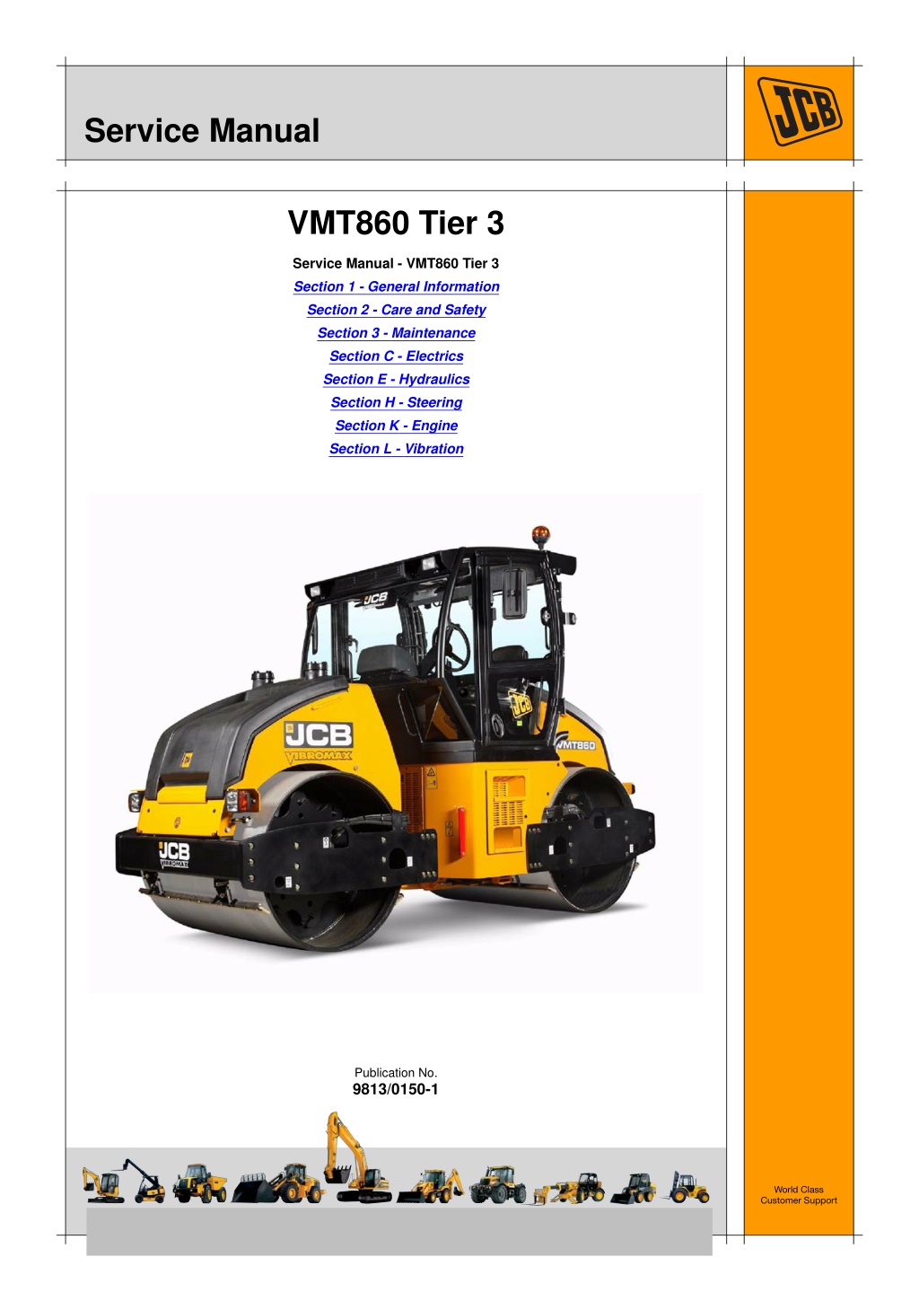
Service Manual VMT860 Tier 3 Service Manual - VMT860 Tier 3 Section 1 - General Information Section 2 - Care and Safety Section 3 - Maintenance Section C - Electrics Section E - Hydraulics Section H - Steering Section K - Engine Section L - Vibration Publication No. 9813/0150-1 World Class Customer Support Copyright 2004 JCB SERVICE. All rights reserved. No part of this publication may be reproduced, stored in a retrieval system, or transmitted in any form or by any other means, electronic, mechanical, photocopying or otherwise, without prior permission from JCB SERVICE. Issued by JCB Technical Publications, JCB Aftermarket Training, Woodseat, Rocester, Staffordshire, ST14 5BW, England. Tel +44 1889 591300 Fax +44 1889 591400
Section 1 - General Information Notes: 1-0 1-0 9813/0150-1
Section 1 - General Information Contents Introduction About This Manual ..................................................................................... 1-1 Identifying Your Machine ........................................................................... 1-3 Page No. Torque Settings Zinc Plated Fasteners and Dacromet Fasteners ....................................... 1-5 Hydraulic Connections ............................................................................... 1-9 Service Tools Numerical List .......................................................................................... 1-13 Tool Detail Reference .............................................................................. 1-14 Service Consumables Sealing and Retaining Compounds ......................................................... 1-19 1-i 1-i
Section 1 - General Information Contents Page No. 1-ii 1-ii
https://www.ebooklibonline.com Hello dear friend! Thank you very much for reading. Enter the link into your browser. The full manual is available for immediate download. https://www.ebooklibonline.com
Section 1 - General Information Introduction About This Manual Machine Model and Serial Number Finally, please remember above all else safety must come first! This manual provides information for the following model(s) in the JCB machine range: Section Numbering T11-005 VMT 860 from SN 2802400 The manual is compiled in sections, the first three are numbered and contain information as follows: Using the Service Manual General Information - includes torque settings and service tools. Care and Safety - includes warnings and cautions pertinent to aspects of workshop procedures etc. Maintenance - includes service schedules and recommended lubricants for all the machine. 1 T11-004 This publication is designed for the benefit of JCB Distributor Service Engineers who are receiving, or have received, training by JCB Technical Training Department. 2 3 These personnel should have a sound knowledge of workshop practice, safety procedures, and general techniques associated with the maintenance and repair of hydraulic earthmoving equipment. The remaining sections are alphabetically coded and deal with Dismantling, Overhaul etc. of specific components, for example: The illustrations in this publication are for guidance only. Where the machines differ, the text and/or the illustration will specify. Attachments Body and Framework, etc. A B General warnings in Section 2 are repeated throughout the manual, as well as specific warnings. Read all safety statements regularly, so you do not forget them. Section contents, technical data, circuit descriptions, operation descriptions etc. are inserted at the beginning of each alphabetically coded section. Renewal of oil seals, gaskets, etc., and any component showing obvious signs of wear or damage is expected as a matter of course. It is expected that components will be cleaned and lubricated where appropriate, and that any opened hose or pipe connections will be blanked to prevent excessive loss of hydraulic fluid and ingress of dirt. Units of Measurement T1-001_2 In this publication, the S.I. system of units is used. For example, liquid capacities are given in litres. The Imperial units follow in parentheses ( ) eg 28 litres (6 gal). Where a torque setting is given as a single figure it may be varied by plus or minus 3%. Torque figures indicated are for dry threads, hence for lubricated threads may be reduced by one third. The manufacturer's policy is one of continuous improvement. The right to change the specification of the machine without notice is reserved. No responsibility will be accepted for discrepancies which may occur between specifications of the machine and the descriptions contained in this publication. 1-1 1-1 9813/0150-1
Section 1 - General Information Introduction About This Manual Left Side, Right Side In this manual, 'left' A and 'right' B mean your left and right when you are seated correctly in the machine. B A Fig 1. Cross References T1-004_2 In this publication, page cross references are made by presenting the subject title printed in bold, italic and underlined. It is preceeded by the 'go to' symbol. The number of the page upon which the subject begins, is indicated within the brackets. For example: K K Cross References ( T T 1-2). 1-2 1-2 9813/0150-1
Section 1 - General Information Introduction Identifying Your Machine Identifying Your Machine Machine Identification Plate Your machine has an identification plate mounted as shown. K K Fig 2. ( T T 1-3). The machine and engine serial numbers can help identify exactly the type of equipment you have. JCB VIBROMAX GmbH SCHAEFERBERG 1 06466 GATERSLEBEN Product Identification Number, PIN, ISO 10261 YEAR OF MANUFACTURE TYPE MAX FRONT AXLE LOAD (kg) MAX REAR AXLE LOAD (kg) OPERATING MASS (kg) EN500-1 ENGINE POWER kW @ RPM, ISO 3046-1 332/N0674 Fig 2. 1-3 1-3 9813/0150-1
Section 1 - General Information Introduction Identifying Your Machine Page left intentionally blank 1-4 1-4 9813/0150-1
Section 1 - General Information Torque Settings Zinc Plated Fasteners and Dacromet Fasteners Torque Settings Zinc Plated Fasteners and Dacromet Fasteners T11-002 Introduction Bolts and Screws Some external fasteners on JCB machines are manufactured using an improved type of corrosion resistant finish. This type of finish is called Dacromet and replaces the original Zinc and Yellow Plating used on earlier machines. Use the following torque setting tables only where no torque setting is specified in the text. Note: Dacromet fasteners are lubricated as part of the plating process, do not lubricate. The two types of fasteners can be readily identified by colour and part number suffix. K K Table 1. Fastener Types ( T T 1-5). Torque settings are given for the following conditions: Condition 1 Table 1. Fastener Types Colour Un-lubricated fasteners Zinc fasteners Yellow plated fasteners Fastener Type Zinc and Yellow Dacromet Part No. Suffix Golden finish 'Z' (e.g. 1315/3712Z) Condition 2 Mottled silver finish 'D' (e.g. 1315/3712D) Zinc flake (Dacromet) fasteners Lubricated zinc and yellow plated fasteners Where there is a natural lubrication. For example, cast iron components Note: As the Dacromet fasteners have a lower torque setting than the Zinc and Yellow fasteners, the torque figures used must be relevant to the type of fastener. Note: A Dacromet bolt should not be used in conjunction with a Zinc or Yellow plated nut, as this could change the torque characteristics of the torque setting further. For the same reason, a Dacromet nut should not be used with a Zinc or Yellow plated bolt. Verbus Ripp Bolts Note: All bolts used on JCB machines are high tensile and must not be replaced by bolts of a lesser tensile specification. Fig 1. Note: Dacromet bolts, due to their high corrosion resistance are used in areas where rust could occur. Dacromet bolts are only used for external applications. They are not used in applications such as gearbox or engine joint seams or internal applications. Torque settings for these bolts are determined by the application. Refer to the relevant procedure for the required settings. 1-5 1-5 9813/0150-1
Section 1 - General Information Torque Settings Zinc Plated Fasteners and Dacromet Fasteners Table 2. Torque Settings - UNF Grade 'S' Fasteners Hexagon (A/F) in. Nm 7/16 11.2 1/2 22.3 9/16 40.0 5/8 64.0 3/4 98.00 13/16 140.0 15/16 196.0 1 1/8 343.0 1 15/16 547.0 1 1/2 814.0 1 7/8 1181.0 2 1/4 1646.0 Bolt Size Condition 1 kgf m 1.1 2.3 4.1 6.5 10.0 14.3 20.0 35.0 55.8 83.0 120.4 167.8 Condition 2 kgf m 1.0 2.0 3.7 5.8 9.0 12.8 18.0 31.5 50.2 74.6 108.4 151.0 in. 1/4 5/16 3/8 7/16 1/2 9/16 5/8 3/4 7/8 1 1 1/8 1 1/4 mm 6.3 7.9 9.5 11.1 12.7 14.3 15.9 19.0 22.2 25.4 31.7 38.1 lbf ft 8.3 16.4 29.5 47.2 72.3 103.2 144.6 253.0 403.4 600.4 871.1 1214.0 Nm 10.0 20.0 36.0 57.0 88.0 126.0 177.0 309.0 492.0 732.0 1063.0 1481.0 lbf ft 7.4 14.7 26.5 42.0 64.9 92.9 130.5 227.9 362.9 539.9 784.0 1092.3 Table 3. Torque Settings - Metric Grade 8.8 Fasteners Hexagon (A/F) Bolt Size Condition 1 Condition 2 ISO Metric Thread M5 M6 M8 M10 M12 M16 M20 M24 M30 M36 mm 5 6 8 10 12 16 20 24 30 36 mm 8 10 13 17 19 24 30 36 46 55 Nm 5.8 9.9 24.0 47.0 83.0 205.0 400.0 690.0 1372.0 2399.0 kgf m 0.6 1.0 2.4 4.8 8.5 20.9 40.8 70.4 139.9 244.6 lbf ft 4.3 7.3 17.7 34.7 61.2 151.2 295.0 508.9 1011.9 1769.4 Nm 5.2 9.0 22.0 43.0 74.0 184.0 360.0 621.0 1235.0 2159.0 kgf m 0.5 0.9 2.2 4.4 7.5 18.8 36.7 63.3 125.9 220.0 lbf ft 3.8 6.6 16.2 31.7 54.6 135.7 265.5 458.0 910.9 1592.4 1-6 1-6 9813/0150-1
Section 1 - General Information Torque Settings Zinc Plated Fasteners and Dacromet Fasteners Table 4. Metric Grade 10.9 Fasteners Hexagon (A/F) Bolt Size Condition 1 Condition 2 ISO Metric Thread M5 M6 M8 M10 M12 M16 M20 M24 M30 M36 mm 5 6 8 10 12 16 20 24 30 36 mm 8 10 13 17 19 24 30 36 46 55 Nm 8.1 13.9 34.0 67.0 116.0 288.0 562.0 971.0 1930.0 3374.0 kgf m 0.8 1.4 3.5 6.8 11.8 29.4 57.3 99.0 196.8 344.0 lbf ft 6.0 10.2 25.0 49.4 85.5 212.4 414.5 716.9 1423.5 2488.5 Nm 7.3 12.5 30.0 60.0 104.0 259.0 506.0 874.0 1737.0 3036.0 kgf m 0.7 1.3 3.0 6.1 10.6 26.4 51.6 89.1 177.1 309.6 lbf ft 5.4 9.2 22.1 44.2 76.7 191.0 373.2 644.6 1281.1 2239.2 Table 5. Metric Grade 12.9 Fasteners Hexagon (A/F) Bolt Size Condition 1 Condition 2 ISO Metric Thread M5 M6 M8 M10 M12 M16 M20 M24 M30 M36 mm 5 6 8 10 12 16 20 24 30 36 mm 8 10 13 17 19 24 30 36 46 55 Nm 9.8 16.6 40.0 80.0 139.0 345.0 674.0 1165.0 2316.0 4049.0 kgf m 1.0 1.7 4.1 8.1 14.2 35.2 68.7 118.8 236.2 412.9 lbf ft 7.2 12.2 29.5 59.0 102.5 254.4 497.1 859.2 1708.2 2986.4 Nm 8.8 15.0 36.0 72.0 125.0 311.0 607.0 1048.0 2084.0 3644.0 kgf m 0.9 1.5 3.7 7.3 12.7 31.7 61.9 106.9 212.5 371.6 lbf ft 6.5 11.1 26.5 53.1 92.2 229.4 447.7 773.0 1537.1 2687.7 1-7 1-7 9813/0150-1
Section 1 - General Information Torque Settings Zinc Plated Fasteners and Dacromet Fasteners Table 6. Torque Settings - Rivet Nut Bolts/Screws Bolt Size ISO Metric Thread mm M3 3 M4 4 M5 5 M6 6 M8 8 M10 10 M12 12 Nm 1.2 3.0 6.0 10.0 24.0 48.0 82.0 kgf m 0.1 0.3 0.6 1.0 2.5 4.9 8.4 lbf ft 0.9 2.0 4.5 7.5 18.0 35.5 60.5 Table 7. Torque Settings - Internal Hexagon Headed Cap Screws (Zinc) Bolt Size ISO Metric Thread M3 2.0 M4 6.0 M5 11.0 M6 19.0 M8 46.0 M10 91.0 M12 159.0 M16 395.0 M18 550.0 M20 770.0 M24 1332.0 Nm kgf m 0.2 0.6 1.1 1.9 4.7 9.3 16.2 40.0 56.0 79.0 136.0 lbf ft 1.5 4.5 8.0 14.0 34.0 67.0 117.0 292.0 406.0 568.0 983.0 1-8 1-8 9813/0150-1
Section 1 - General Information Torque Settings Hydraulic Connections Hydraulic Connections T11-003 'O' Ring Face Seal System Adaptors Screwed into Valve Blocks Adaptor screwed into valve blocks, seal onto an 'O' ring which is compressed into a 45 seat machined into the face of the tapped port. Table 8. Torque Settings - BSP Adaptors BSP Adaptor Size in. mm 1/4 19.0 3/8 22.0 1/2 27.0 5/8 30.0 3/4 32.0 1 38.0 1 1/4 50.0 Hexagon (A/F) Nm 18.0 31.0 49.0 60.0 81.0 129.0 206.0 kgf m 1.8 3.2 5.0 6.1 8.2 13.1 21.0 lbf ft 13.0 23.0 36.0 44.0 60.0 95.0 152.0 Table 9. Torque Settings - SAE Connections Hexagon (A/F) mm 15.9 20.0 - 28.0 19.1 46.0 - 54.0 22.2 95.0 - 105.0 27.0 130.0 - 140.0 1 1/16 - 12 31.8 1 5/16 - 12 38.1 1 5/8 47.6 SAE Tube Size 4 6 8 10 12 16 20 SAE Port Thread Size 7/16 - 20 9/16 - 18 3/4 - 16 7/8 - 14 Nm kgf m 2.0 - 2.8 4.7 - 5.5 9.7 - 10.7 13.2 - 14.3 19.4 - 21.4 29.6 - 31.6 28.5 - 38.7 lbf ft 16.5 - 18.5 34.0 - 40.0 69.0 - 77.0 96.0 - 104.0 141.0 - 155.0 216.0 - 230.0 210.0 - 280.0 190.0 - 210.0 290.0 - 310.0 280.0 - 380.0 1-9 1-9 9813/0150-1
Section 1 - General Information Torque Settings Hydraulic Connections Hoses Screwed into Adaptors Fig 2. Hoses 2-B screwed into adaptors 2-A seal onto an `O' ring 2-C which is compressed into a 45 seat machined into the face of the adaptor port. Note: Dimension 2-D will vary depending upon the torque applied. Table 10. BSP Hose - Torque Settings Hexagon (A/F) mm 14.0 14.0 - 16.00 19.0 24.0 - 27.0 22.0 33.0 - 40.0 27.0 44.0 - 50.0 30.0 58.0 - 65.0 32.0 84.0 - 92.0 38.0 115.0 - 126.0 50.0 189.0 - 200.0 55.0 244.0 - 260.0 BSP Hose Size in. 1/8 1/4 3/8 1/2 5/8 3/4 1 1 1/4 1 1/2 Nm kgf m 1.4 - 1.6 2.4 - 2.7 3.4 - 4.1 4.5 - 5.1 5.9 - 6.6 8.6 - 9.4 11.7 - 12.8 19.3 - 20.4 24.9 - 26.5 lbf ft 10.3 - 11.8 17.7 - 19.9 24.3 - 29.5 32.4 - 36.9 42.8 - 47.9 61.9 - 67.8 84.8 - 92.9 139.4 - 147.5 180.0 - 191.8 1-10 1-10 9813/0150-1
Section 1 - General Information Torque Settings Hydraulic Connections Adaptors into Component Connections with Bonded Washers Table 11. BSP Adaptors with Bonded Washers - Torque Settings BSP Size Nm in. 1/8 20.0 1/4 34.0 3/8 75.0 1/2 102.0 5/8 122.0 3/4 183.0 1 203.0 1 1/4 305.0 1 1/2 305.0 kgf m 2.1 3.4 7.6 10.3 12.4 18.7 20.7 31.0 31.0 lbf ft 15.0 25.0 55.0 75.0 90.0 135.0 150.0 225.0 225.0 1-11 1-11 9813/0150-1
Section 1 - General Information Torque Settings Hydraulic Connections 'Torque Stop' Hose System Fig 3. `Torque Stop' Hoses 3-B screwed into adaptors 3-A seal onto an 'O' ring 3-C which is compressed into a 45 seat machined in the face of the adaptor port. To prevent the 'O' ring being damages as a result of over tightening, 'Torque Stop' Hoses have an additional shoulder 3-D, which acts as a physical stop. Note: Minimum dimension 3-E fixed by shoulder 3-D. Table 12. BSP `Torque Stop' Hose - Torque Settings BSP Hose Size Hexagon (A/F) in. mm 1/8 14.0 1/4 19.0 3/8 22.0 1/2 27.0 5/8 30.0 3/4 32.0 1 38.0 1 1/4 50.0 1 1/2 55.0 Nm 14.0 27.0 40.0 55.0 65.0 95.0 120.0 189.0 244.0 kgf m 1.4 2.7 4.1 5.6 6.6 9.7 12.2 19.3 24.9 lbf ft 10.0 20.0 30.0 40.0 48.0 70.0 89.0 140.0 180.0 Table 13. 1-12 1-12 9813/0150-1
Section 1 - General Information Service Tools Numerical List The tools listed in the table are special tools required for carrying out the procedures described in this manual. These tools are available from JCB Service. details of all tools, including the content of kits and sets, refer to Tool Detail Reference, Section 1. Note: Tools other than those listed will be required. It is expected that such general tools will be available in any well equipped workshop or be available locally from any good tool supplier. Some tools are available as kits or sets, the part numbers for parts within such kits or sets are not listed here. For full Part Number - - - - - - Description See Section Bonded Washers - see Tool Detail Reference (Section 1) for content Female Cone Blanking Caps - see Tool Detail Reference (Section 1) for content Female Connectors - see Tool Detail Reference (Section 1) for content Hydraulic Flow Test Equipment - see Tool Detail Reference (Section 1) for content Male Adapters - BSP x BSP - see Tool Detail Reference (Section 1) for content Male Adapters - BSP x NPT (USA only) - see Tool Detail Reference (Section 1) for content Male Cone Blanking Caps - see Tool Detail Reference (Section 1) for content Pressure Test Points - Adaptors - see Tool Detail Reference (Section 1) for content Pressure Test Points - 'T' Adaptors - see Tool Detail Reference (Section 1) for content Hydraulic Circuit Pressure Test Kit - see Tool Detail Reference (Section 1) for content Hose Gauge Gauge Digital Tachometer Hyd. Oil Temperature Probe Fluke Meter Gauge Connector Vibromax male to JCB female threaded adaptor E E E E E E - - - 892/00253 892/00254 892/00279 892/00280 892/00284 892/00285 892/00298 892/00346 892/00347 892/01246 E E E E E E E C C C E E E E E C 892/01247 892/12345 892/00285 JCB male to Vibromax female threaded adaptor Frequency and Vibration Measuring Tool 100 amp Shunt 1-13 1-13 9813/0150-1
Section 1 - General Information Service Tools Tool Detail Reference Tool Detail Reference Section C - Electrics Note: Not all service tools are illustrated. Fig 1. 892/00298 Fluke Meter Fig 2. 892/00285 Hydraulic Temperature Probe Fig 3. 892/00284 Venture Microtach Digital Tachometer 1-14 1-14 9813/0150-1
Section 1 - General Information Service Tools Tool Detail Reference Section E - Hydraulics Note: Not all service tools are illustrated. Male Adapters - BSP x BSP 3/8 in. x 1/4 in. 3/8 in. x 3/8 in. 3/8 in. x 3/8 in. taper 1/2 in. x 1/4 in. 1/2 in. x 3/8 in. 1/2 in. x 1/2 in. 5/8 in. x 1/2 in. 3/4 in. x 3/8 in. 3/4 in. x 1/2 in. 3/4 in. x 3/4 in. 3/4 in. x 1 in. 3/4 in. x 1.1/4 in. 1 in. x 1.1/4 in. 1606/2052 1604/0003A 892/00071 1606/0004 1606/0007A 1604/0004A 1606/0017 1606/0008 1606/0009 1604/2055 1606/0012 1606/0014 1606/0015 Fig 4. Male Adaptors Male Adapters - BSP x NPT (USA only) 3/8 in. x 1/4 in. 1/2 in. x 1/4 in. 3/8 in. x 3/8 in. 1/2 in. x 3/8 in. 816/00439 816/00440 816/15007A 816/15008 892/00255 892/00256 892/00257 892/00258 816/15118 892/00259 892/00260 892/00261 1/4 in. BSP x Test Point 3/8 in. BSP x Test Point 1/2 in. BSP x Test Point 5/8 in. BSP x Test Point 3/4 in. BSP x Test Point 1 in BSP x Test Point 1.1/4 in. BSP x Test Point 5/8 in. UNF x Test Point Fig 5. Pressure Test Adapters 816/55045 816/55038 816/55040 892/00263 892/00264 1/4 in. M BSP x 1/4 in. F BSP x Test Point 3/8 in. M BSP x 3/8 in. F BSP x Test Point 1/2 in. M BSP x 1/2 in. F BSP x Test Point 5/8 in. M BSP x 5/8 in. F BSP x Test Point 3/4 in. M BSP x 3/4 in. F BSP x Test Point 892/00265 892/00266 892/00267 1 in. M BSP x 1 in. F BSP x Test Point 1.1/4 in. M BSP x 1.1/4 in. F BSP x Test Point 1.1/4 in. M BSP x 1.1/2 in. F BSP x Test Point Fig 6. Pressure Test 'T' Adapters 1-15 1-15 9813/0150-1
Section 1 - General Information Service Tools Tool Detail Reference 892/00047 892/00048 892/00049 816/50043 892/00051 816/50005 816/60096 816/00017 3/8 in. BSP (A) x 1/4 in. BSP (B) 1/2 in. BSP (A) x 1/4 in. BSP (B) 5/8 in. BSP (A) x 1/4 in. BSP (B) 3/4 in. BSP (A) x 1/4 in. BSP (B) 1 in. BSP (A) x 1/4 in. BSP (B) 1/2 in. BSP (A) x 1/2 in. BSP (B) 3/4 in. BSP (A) x 3/4 in. BSP (B) 1 in. BSP (A) x 1 in. BSP (B) Fig 7. 'T' Adapters 892/00055A 892/00056A 892/00057 892/00058A 892/00059A 892/00060 1/4 in. BSP 3/8 in. BSP 1/2 in. BSP 5/8 in. BSP 3/4 in. BSP 1 in. BSP Fig 8. Female Blanking Caps 816/90045 816/00189A 816/00190A 816/90022 816/90274 816/90205 1/4 in. BSP 3/8 in. BSP 1/2 in. BSP 5/8 in. BSP 3/4 in. BSP 1 in. BSP Fig 9. Male Cone Blanking Caps 892/00074 892/00075 892/00076 892/00077 3/8 in. BSP x 3/8 in. BSP 1/2 in. BSP x 1/2 in. BSP 5/8 in. BSP x 5/8 in. BSP 3/4 in. BSP x 3/4 in. BSP Fig 10. Female Connectors 1406/0011 1406/0018 1406/0014 1406/0021 1406/0029 1/4 in. BSP 1/2 in. BSP 5/8 in. BSP 3/4 in. BSP 1.1/4 in. BSP Fig 11. Bonded Washers 1-16 1-16 9813/0150-1
Section 1 - General Information Service Tools Tool Detail Reference 892/00268 892/00269 892/00273 892/00293 892/00270 1406/0021 1604/0006A 1612/2054 892/00271 892/00272 816/20008 892/00275 892/00276 892/00277 1606/0015 892/00078 1604/0008 1604/0008 816/20013 Flow Monitoring Unit Sensor Head 0 - 100 l/min (0 - 22 UK gal/min) Sensor Head 0 - 380 l/min (0 - 85.5 UK gal/min) Connector Pipe Load Valve Bonded Washer Adapter 3/4 in M x 3/4 in M BSP Adapter 3/4 in F x 3/4 in M BSP Adapter 3/4 in F x 5/8 in M BSP Adapter 5/8 in F x 3/4 in M BSP Adapter 3/4 in F x 1/2 in M BSP Adapter 1/2 in F x 3/4 in M BSP Adapter 3/4 in F x 3/8 in M BSP Adapter 3/8 in F x 3/4 in M BSP Adapter 1.1/4 in M BSP x 1 in M BSP Connector 1 in F x 1 in F BSP Adapter 1 in M x 1 in M BSP Adapter 1 in M x 3/4 in M BSP Adapter 3/4 in F x 1 in M BSP Fig 12. Flow Test Equipment 892/00201 Replacement Gauge 0-20 bar (0-300 lbf/in2) 892/00202 Replacement Gauge 0-40 bar (0-600 lbf/in2) 1 892/00203 Replacement Gauge 0-400 bar (0-6000 lbf/in2) Replacement Hose Seal Kit for 892/00254 (can also be used with probe 892/00706) Test Probe Connector - Hose to gauge 2 3 892/00254 993/69800 892/00706 892/00347 Fig 13. 892/ 00253 Hydraulic Circuit Pressure Test Kit 1-17 1-17 9813/0150-1
Section 1 - General Information Service Tools Tool Detail Reference 892/00280 Pressure Gauge 0-600 bar (0-9000 lbf/in2) 892/00279 Pressure Gauge 0-400 bar (0-6000 lbf/in2) 892/00346 Pressure Gauge 0-70 bar (0-1000 lbf/in2) Connector Hose 892/00347 892/00254 Fig 14. Hydraulic Circuit Test Gauges and Connections Fig 15. Adaptor (item A) Item Part No A 892/01247 JCB male to Vibromax female threaded adaptor - Connects JCB female test hose to male Vibromax test point B 892/01246 Vibromax male to JCB female threaded adaptor - Connects Vibromax female test hose to JCB male test point Description Qty a/r Fig 16. 892/12345 Frequency and Vibration Measuring Tool Allows the service engineer to measure the frequency of the vibrating drum (it will also measure engine speed on any type of machinery). a/r Note: In order to use JCB test hoses and gauges on JCB Vibromax machines (and where applicable, other manufacturers machines fitted with M16 X2mm test points) a special adaptor A is required. For JCB Vibromax dealers or customers that already have JCB Vibromax compatible test hoses a `special adaptor' B (not shown) will be required to connect to JCB test points 1-18 1-18 9813/0150-1
Section 1 - General Information Service Consumables Sealing and Retaining Compounds Service Consumables Sealing and Retaining Compounds T11-001_3 Table 1. Type JCB Multi-Gasket Description A medium strength sealant suitable for all sizes of gasket flanges, and for hydraulic fittings of 25-65 mm diameter. A high strength locking fluid for use with threaded components. Gasketing for all sizes of flange where the strength of the joint is important. For all retaining parts which are unlikely to be dismantled. A medium strength locking fluid for sealing and retaining nuts, bolts, and screws up to 50 mm diameter, and for hydraulic fittings up to 25 mm diameter. A high strength locking fluid for sealing and retaining nuts, bolts, and screws up to 50 mm diameter, and for hydraulic fittings up to 25 mm diameter. A medium strength thread sealing compound. A cleaning primer which speeds the curing rate of anaerobic products. Part No. 4102/1212 Quantity 50 ml JCB High Strength Threadlocker 4102/0551 50 ml JCB Retainer (High Strength) 4101/0651 50 ml JCB Threadlocker and Sealer 4101/0250 4101/0251 10 ml 50 ml JCB Threadlocker and Sealer (High Strength) 4101/0550 4101/0552 10 ml 200 ml JCB Threadseal JCB Activator 4102/1951 4104/0251 4104/0253 4104/1557 50 ml 200 ml (Aerosol) 1 ltr (Bottle) 400 ml (Aerosol) JCB Cleaner/Degreaser For degreasing components prior to use of anaerobic adhesives and sealants. For one pane of glass; comprises of: Direct Glazing Kit 993/55700 1 x Ultra Fast Adhesive (310 ml) 1 x Active Wipe 205 (30 ml) 1 x Black Primer 206J (30 ml) plus applicator nozzle etc. For direct glazing. For direct glazing. For direct glazing. To seal butt jointed glass. To seal plastic to metal joints. To finish exposed edges of laminated glass. Ultra Fast Adhesive Active Wipe 205 Black Primer 206J Clear Silicone Sealant Plastic to Metal Bonder Black Polyurethane Sealant 4103/2109 4104/1203 4201/4906 4102/0901 4103/0956 4102/2309 310 ml 250 ml 30 ml 50 g 310 ml 1-19 1-19 9813-0150-1
Section 1 - General Information Service Consumables Sealing and Retaining Compounds Page left intentionally blank 1-20 1-20 9813-0150-1
Section 2 - Care and Safety Notes: 2-0 2-0 9813/0150-1
Section 2 - Care and Safety Contents Safety Notices Important Information ................................................................................ 2-1 Safety Check List ....................................................................................... 2-2 Safety Labels ........................................................................................... 2-12 Page No. 2-i 2-i
Section 2 - Care and Safety Contents Page No. 2-ii 2-ii
Section 2 - Care and Safety Safety Notices Important Information T1-042 The Operator Manual Safety Warnings !MWARNING This safety alert system identifies important safety messages in this manual. When you see this symbol, be alert, your safety is involved, carefuly read the message that follows, and inform other operators. You and others can be killed or seriously injured if you operate or maintain the machine without first studying the Operator Manual. You must understand and follow the instructions in the Operator Manual. If you do not understand anything, ask your employer or JCB dealer to explain it. In this publication and on the machine, there are safety notices. Each notice starts with a signal word. The signal word meanings are given below. INT-1-4-2 Do not operate the machine without an Operator Manual, or if there is anything on the machine you do not understand. !MDANGER Denotes an extreme hazard exists. If proper precautions are not taken, it is highly probable that the operator (or others) could be killed or seriously injured. Treat the Operator Manual as part of the machine. Keep it clean and in good condition. Replace the Operator Manual immediately if it is lost, damaged or becomes unreadable. INT-1-2-1 !MWARNING Denotes a hazard exists. If proper precautions are not taken, the operator (or others) could be killed or seriously injured. INT-1-2-2 !MCAUTION Denotes a reminder of safety practices. Failure to follow these safety practices could result in injury to the operator (or others) and possible damage to the machine. INT-1-2-3 2-1 2-1 9813/0150-1
Suggest: If the above button click is invalid. Please download this document first, and then click the above link to download the complete manual. Thank you so much for reading
Section 2 - Care and Safety Safety Notices Safety Check List Safety Check List Safety - Yours and Others General Safety INT-1-3-1_3 T1-043 !MWARNING All machinery can be hazardous. When a machine is correctly operated and properly maintained, it is a safe machine to work with. But when it is carelessly operated or poorly maintained it can become a danger to you (the operator) and others. To operate the machine safely you must know the machine and have the skill to use it. You must abide by all relevant laws, health and safety regulations that apply to the country you are operating in. The Operator Manual instructs you on the machine, its controls and its safe operation; it is not a training manual. If you are a new operator, get yourself trained in the skills of using a machine before trying to work with it. If you don't, you will not do your job well, and you will be a danger to yourself and others. In this manual and on the machine you will find warning messages. Read and understand them. They tell you of potential hazards and how to avoid them. If you do not fully understand the warning messages, ask your employer or JCB distributor to explain them. But safety is not just a matter of responding to the warnings. All the time you are working on or with the machine you must be thinking what hazards there might be and how to avoid them. INT-1-4-1 !MWARNING Care and Alertness Do not work with the machine until you are sure that you can control it. All the time you are working with or on the machine, take care and stay alert. Always be careful. Always be alert for hazards. Do not start any job until you are sure that you and those around you will be safe. INT-1-3-5 !MWARNING If you are unsure of anything, about the machine or the job, ask someone who knows. Do not assume anything. Clothing You can be injured if you do not wear the proper clothing. Loose clothing can get caught in the machinery. Wear protective clothing to suit the job. Examples of protective clothing are: a hard hat, safety shoes, safety glasses, a well fitting overall, ear- protectors and industrial gloves. Keep cuffs fastened. Do not wear a necktie or scarf. Keep long hair restrained. Remove rings, watches and personal jewellery. Remember BE CAREFUL BE ALERT BE SAFE INT-1-3-6_2 !MWARNING Alcohol and Drugs It is extremely dangerous to operate machinery when under the influence of alcohol or drugs. Do not consume alcoholic drinks or take drugs before or while operating the machine or attachments. Be aware of medicines which can cause drowsiness. INT-1-3-9_2 2-2 2-2 9813/0150-1
https://www.ebooklibonline.com Hello dear friend! Thank you very much for reading. Enter the link into your browser. The full manual is available for immediate download. https://www.ebooklibonline.com