Understanding Forces in Trusses for Civil Engineering Studies
Trusses are essential in engineering as they offer stability and strength by forming triangulated patterns. This article explains the concept of trusses, reactions at supports, and provides a sample problem to determine reactions. It discusses the importance of triangulated shapes, pin joint and roller support types, and the method to calculate reactions. Understanding forces in trusses is crucial for designing stable structures like buildings and bridges.

Download Presentation

Please find below an Image/Link to download the presentation.
The content on the website is provided AS IS for your information and personal use only. It may not be sold, licensed, or shared on other websites without obtaining consent from the author. Download presentation by click this link. If you encounter any issues during the download, it is possible that the publisher has removed the file from their server.
E N D
Presentation Transcript
Analysing Forces in Trusses YEAR 12 ENGINEERING STUDIES CIVIL STRUCTURES
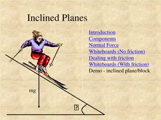
A truss is a structural frame used in engineering.A truss consists of straight bars known as members, that are connected at each endusing a joint. The members arearranged in a triangulated pattern. Why? Consider the stability of two structures, a square and a triangle. Astructure of any other configuration other than a triangle can be pushedout of shape, without changing any of the member's lengths. Triangulated shapes retain their shape. Therefore, rectangular frames, commonly found in buildings as well as bridges, are always braced withanother member to form a triangle. Trusses are used because theycan take a much greater load than a beam, as well as spanning a much greater distance. When spanning a distance, the truss must be supported at each end. As thetruss will exerta forceon these supports, itis necessary that thesupports balance this force with a reaction at thesupport.
Reactions at supports There are two different types of supports generally found in supporting civil structures: Pin joint roller support. Pin joint The pin joint locks the truss in position. It does not allow any sideways movement but may allow some rotation. It may also be referred to as a hinge. The reaction at this joint is to balance any vertical loading and any horizontal loading on the truss. The reaction will have an unknown magnitude and direction. This is represented by a wriggly arrow. For easier calculations, it is generally more convenient to represent this reaction as two components: one vertical and one horizontal. By doing this, you still have two unknowns, but now the unknowns are two magnitudes instead of a magnitude and a direction.
Roller Support The roller support joint is essential in most civil structures, particularly those made from steel, as it is necessary to counteract any expansion or contraction due to temperature changes. It allows unrestricted movement in one direction. The joint may be a smooth-sliding joint or be placed on rollers. The roller support is represented by a graphic shown in figure 2.11. The reaction is a vector that acts perpendicular to the roller's surface.
Sample Problem Examine the method used to determine the reactions at the supports for asimple beam to be used to support a walkway leading on to a bridge or connect buildings together shown in figure 2.13. The first step in solving this problem is to draw a free body diagram of all the forces that are acting on the beam. This should also indicate the reactions at the supports. At the pin joint A, the reaction is shown as a horizontal and a vertical component. At the roller joint B, the reaction will be vertical, as the roller surface is horizontal. The directions (or senses) of the reactions are assumed and may not be correct. These maybe corrected during the calculations of the problem.
It is also a good idea to convert any inclined loadings into their horizontal and vertical components. There are three unknowns (two at the pin joint and one at the roller), so itis necessary to have three equations in order to be able to solve the problem. There are three conditions for equilibrium: All three equations are used to solve the reactions at the supports. You would start by taking moments ( ? = 0) about the pin joint. Two of the unknowns can be eliminated, RAHand RAVbecause both the components pass through the pin, so they create no moment. Remember, the moment of a force is found by multiplying the force by the perpendicular distance away from the point to the line of action of the force (M = F x d). For RAHand RAV d = 0, so the moments created by these forces are also = 0 Since the Moment of a force can act clockwise or counterclockwise , we use a convention that a Moment acting in a counterclockwise direction is positive ie.