JCB VIBROMAX 255 265 TANDEM ROLLER Service Repair Manual Instant Download
Please open the website below to get the complete manualnn//

Download Presentation

Please find below an Image/Link to download the presentation.
The content on the website is provided AS IS for your information and personal use only. It may not be sold, licensed, or shared on other websites without obtaining consent from the author. Download presentation by click this link. If you encounter any issues during the download, it is possible that the publisher has removed the file from their server.
E N D
Presentation Transcript
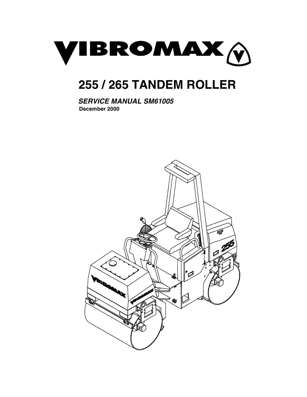
255 / 265 TANDEM ROLLER SERVICE MANUAL SM61005 December 2000
table of contents SECTION ONE GENERAL INFORMATION MACHINE DESCRIPTION...............................................................................1 - 3 SAFETY, GENERAL........................................................................................1 - 7 SAFETY, PERSONAL......................................................................................1 - 7 SAFETY, MACHINE OPERATION ..................................................................1 - 8 SAFETY, MAINTENANCE.............................................................................1 - 10 GENERAL INFORMATION............................................................................1 - 12 STANDARD TORQUE DATA ........................................................................1 - 13 METRIC/USA CONVERSIONS .....................................................................1 - 14 MACHINE SPECIFICATIONS........................................................................1 - 15 FLUID SPECIFICATIONS..............................................................................1 - 17 DIESEL FUEL SPECIFICATION....................................................................1 - 18 ENGINE OIL SPECIFICATION......................................................................1 - 19 SECTION TWO ENGINE R&I ENGINE REMOVAL & INSTALLATION...........................................................2 - 3 SECTION THREE ELECTRICAL CIRCUITS INSTRUMENT PANEL.....................................................................................3 - 2 Instrument panel, left side..........................................................................3 - 3 Combination indicator.................................................................................3 - 4 Instrument panel, right side ........................................................................3 - 5 OPERATOR S CONSOLE...............................................................................3 - 6 ELECTRICAL INFORMATION.........................................................................3 - 8 RELAY LOCATION CHART.............................................................................3 - 9 FUSE LOCATION CHART...............................................................................3 - 9 UNDERSTANDING ELECTRICAL SCHEMATICS.......................................3 - 11 UNDERSTANDING RELAYS.........................................................................3 - 14 EMERGENCY STOP CIRCUIT......................................................................3 - 17 STARTER/ CHARGING CIRCUIT .................................................................3 - 19 UNDERSTANDING BATTERIES...................................................................3 - 19 UNDERSTANDING ALTERNATORS.......................................................3 - 21 STARTER SYSTEM DIAGNOSTICS.............................................................3 - 25 i
table of contents NEUTRAL SWITCH CIRCUIT........................................................................3 - 29 INSTRUMENTATION PANEL........................................................................3 - 31 COMBINATION INDICATOR....................................................................3 - 32 OPERATOR S CONSOLE.............................................................................3 - 33 PARKING BRAKE CIRCUIT..........................................................................3 - 35 VIBRATION CONTROL CIRCUIT..................................................................3 - 35 SPRINKLER CIRCUIT...................................................................................3 - 37 ACCESSORY SOCKETS ..............................................................................3 - 37 SPRINKLER CIRCUIT ("K" option)................................................................3 - 39 LIGHTING CIRCUIT.......................................................................................3 - 41 HAZARD/ DIRECTIONAL CIRCUIT...............................................................3 - 41 BACK-UP ALARM..........................................................................................3 - 42 WIRE HARNESS LAYOUT............................................................................3 - 43 WIRE HARNESS 7131/80115 .......................................................................3 - 46 WIRE CHART 7131/80115 ............................................................................3 - 49 WIRE HARNESS 7131/80255 .......................................................................3 - 51 WIRE CHART 7131/80255 ............................................................................3 - 55 ELECTRICAL SCHEMATICS ........................................................................3 - 59 SECTION FOUR HYDRAULIC SYSTEMS PROPULSION DRAWINGS.............................................................................4 - 2 PROPULSION SYSTEM..................................................................................4 - 5 PROPULSION SYSTEM DIAGNOSTICS...................................................4 - 5 VIBRATION DRAWINGS.................................................................................4 - 7 VIBRATION SYSTEM....................................................................................4 - 10 VIBRATION SYSTEM DIAGNOSTICS.....................................................4 - 11 STEERING DRAWINGS................................................................................4 - 12 STEERING SYSTEM.....................................................................................4 - 15 STEERING SYSTEM DIAGNOSTICS......................................................4 - 15 HYDRAULIC RESERVOIR............................................................................4 - 16 HYDRAULIC OIL FILTER..............................................................................4 - 17 HYDRAULIC OIL RESERVOIR .....................................................................4 - 17 BRAKE SYSTEM DRAWINGS ......................................................................4 - 18 PARKING BRAKES .......................................................................................4 - 21 PARKING BRAKE DIAGNOSTICS...........................................................4 - 21 HYDRAULIC TEST PORTS...........................................................................4 - 22 HYDRAULIC COMPONENT LOCATIONS....................................................4 - 30 ii
table of contents HYDRAULIC SCHEMATIC............................................................................4 - 31 HYDRAULIC SCHEMATIC ( K model).........................................................4 - 32 K MODEL SYSTEMS ..................................................................................4 - 33 HYDRAULIC COMPONENTS POCLAIN MC05 PROPULSION MOTOR......................................................4 - 38 SAUER/SUNDSTRAND SERIES 42 PROPULSION PUMP..........................4 - 41 SECTION FIVE POWER TRAIN DRUM REMOVAL..........................................................................................5 - 11 DRIVE MOTOR REMOVAL...........................................................................5 - 11 DRIVE MOTOR REPAIR ...............................................................................5 - 13 DRIVE MOTOR INSTALLATION...................................................................5 - 13 DRUM DRIVE BEARING REMOVAL.............................................................5 - 13 DRUM BEARING INSTALLATION.................................................................5 - 15 DRUM INSTALLATION..................................................................................5 - 15 PNEUMATIC TIRE DRIVE.............................................................................5 - 16 SECTION SIX PARKING BRAKE SYSTEM PARK BRAKE TESTING..................................................................................6 - 5 BRAKE RELEASE FOR TOWING...................................................................6 - 5 TOWING PROCEDURE.............................................................................6 - 6 BRAKE REPAIRS............................................................................................6 - 8 SECTION SEVEN VIBRATORY SYSTEM VIBRATORY SHAFT REMOVAL.....................................................................7 - 9 INSTALLING VIBRATORY SHAFT................................................................7 - 11 SECTION EIGHT STEERING SYSTEM iii
https://www.ebooklibonline.com Hello dear friend! Thank you very much for reading. Enter the link into your browser. The full manual is available for immediate download. https://www.ebooklibonline.com
table of contents SECTION NINE CHASSIS FRAME.............................................................................................................9 - 3 HOOD & DOOR PANELS................................................................................9 - 4 OPERATOR PLATFORM ................................................................................9 - 5 WATER TANK..................................................................................................9 - 6 WATER TANK COATING................................................................................9 - 7 ROLL OVER PROTECTIVE STRUCTURE (ROPS)........................................9 - 8 SUN ROOF....................................................................................................9 - 10 SECTION TEN ATTACHMENTS WATER SPRINKLER SYSTEM.....................................................................10 - 2 DRUM SCRAPERS........................................................................................10 - 6 ROAD LIGHT KIT 87130/20120.....................................................................10 - 8 WORK LIGHT KIT 87130/20100..................................................................10 - 10 iv
SECTION ONE GENERAL INFORMATION 1 - 1
SM61005 - SECTION ONE GENERAL INFORMATION Built with serviceability in mind. 1 - 2
SM61005 - SECTION ONE GENERAL INFORMATION MACHINE DESCRIPTION The 255/265 Series vibratory roller is a redesign of the 253/263. The machine remains a 2.5 metric ton, tandem drum machine with articulated steering, hydrostatic drive and a hydraulically driven vibration system. The 255 has a 1000 mm (39 inch) drum width while the 265 is a 1200 mm (47 inch) drum width version. These machines are also offered with a K version which is a combination roller built with pneumatic tires in place of the rear drum. A Kubota D1403B, water cooled, three cylinder in-line diesel engine, mounted in the rear chassis, provides the power for the machine. The standard engine has a 29.0 Net Horse Power rating at 2600 RPM. An optional high horsepower Kubota D1403B (37 horsepower) is also available. Both engines meet the latest exhaust emissions standards. A Sauer Sunstrand hydrostatic propulsion pump provides oil for the front and rear Poclain, fixed displacement, drum drive motors in a parallel path. On the K model combination roller there are three propulsion motors in parallel. Propulsion system controls are enhanced with the addition of a high and low operating range. The motors are located on the right hand side of the drums and are connected directly to the drum. The vibration system consists of a fixed displacement gear pump mounted to the back of the propulsion pump. This gear pump drives the two gear motors (one on each drum, left hand side) in a series flow path, with options of vibration to the front drum only, rear drum only, both drums or neither drum. Oil from the vibration circuit passes through an air to oil cooler at the engine radiator. The exciter shafts and the drum bearings are oil lubricated, eliminating the need for grease zerks. Pressure testing of the hydraulic system has been simplified by the location of a test station inside the left side access door. Pressure testing of the drive, charge, vibratory and steering systems can be performed from this one location. 1 - 3
SM61005 - SECTION ONE GENERAL INFORMATION The electrical system consists of the stan- Front and rear parking brakes are provided dard starter, battery and charging circuit on the 255/265. The drum brakes are inte- along with optional lighting, hazard and gral to the drive motors. The brakes are directional lights. The instrument panel spring applied / hydraulically released and includes switches for vibration, sprinklers, are controlled by a switch on the dash and lights and brakes along with the standard by an emergency stop switch on the right instrument cluster of warning lights and an operators console. A brake release valve hour meter. An emergency stop button is and a brake hand pump are located under located right of the operator s seat. All elec- the hood on the left side of the machine. trical fuses and relays are located behind a These items provide for brake release door panel on the right side of the opera- when towing a disabled machine. tors platform. A steering pump, mounted to the back of A 53 gallon water tank is located on the the vibration pump, provides oil for the front chassis, providing water for the steering control valve and a single steering asphalt sprinkler system. The tank s modu- cylinder at the articulation joint. The joint is lar design allows for easy removal if neces- maintenance free, providing 40 degrees of sary. On the K model combination roller articulation and 15 degrees of oscillation. the water tank has two separate compart- An articulation joint safety lock completes ments and the system has two water the steering system. pumps to allow for the use of a special spray on the pneumatic tires. Pressurized The return oil flow from the vibratory circuit sprinkler bars with spray nozzles on each and the steering circuit passes through a drum, or tires on the K model, complete 10 micron oil filter mounted in the top of the the water system. Spring loaded scrapers hydraulic reservoir. A filter bypass and a are provided on the front and rear of each pressure differential switch completes the drum. This arrangement keeps a constant filter circuit. The hydraulic reservoir is scraper pressure against the drum. located below the operators platform on the left side of the rear chassis. 1 - 4
SM61005 - SECTION ONE GENERAL INFORMATION SERIAL NUMBERS 1 2 3 4 5 6 7 8 Model / Serial Number Front Drum Drive Motor S/N Rear Drum Drive Motor S/N Steering Unit S/N Front Vibratory Motor S/N Rear Vibratory Motor S/N Hydraulic Pumps S/N Engine S/N 1 - 5
SM61005 - SECTION ONE GENERAL INFORMATION IDENTIFYING MACHINE COMPONENTS 1 2 3 4 5 6 7 8 9 Articulation joint Smooth drum Lifting eye Operator s stand Battery Hydraulic tank Engine Drum drive motor Rubber buffer Scraper 11 12 13 14 15 16 17 18 19 20 Spring loaded brake Water tank Fuel tank Air filter canister Water - oil cooler Roll over protection Vibration motor Steering cylinder Hydraulic pumps Sun roof 10 1 - 6
SM61005 - SECTION ONE GENERAL INFORMATION SAFETY, GENERAL The information in this manual does not replace any safety rules and laws used in your area. Before you operate this machine, learn the rules and laws for your area and make sure your machine has the correct equipment according to these rules and regulations. A fire can cause injury or death. Always have a fire extinguisher on the job site near the machine. Make sure the fire extin- guisher is serviced according to the manufacturer s instructions. Your safety and the safety of other persons in the work area are dependent on your correct operation of this machine. Foreign materials and loose objects on the steps, hand rails, and in the operator s compart- ment can cause accidents and injury. Keep the steps, hand rails, and opera- tor s compartment clear at all times. Know the location and function of all machine controls. Clear the area of other persons before you start the engine. Always use the seat belt when operating the machine. Make sure the buckle for the seat is fastened correctly. Check all controls in a safe area before you operate the machine. Understand the limits of the machine. Do not try to do too much too fast. Make sure cab win- dows are clean and unobstructed. Keep the machine under control at all times. Know and under- stand the arrangements for movement of trucks, machines, and persons on your job site. Understand and follow the instructions of flagmen, road signs, or signals. SPARK ARRESTER NOTE: Rules or laws in some areas can make it necessary for this machine to be equipped with a spark arrester or spark arrester muffler. Check the rules or laws in your area. Always wear the SAFETY, PERSONAL proper ear protection when operating this machine. Permanent hearing loss can result from extended exposure to loud noises. Loose clothing and jewelry can cause an accident. Do not wear loose clothing or jewelry that can catch on controls, etc. Do wear safety shoes, hard hat, heavy gloves, etc. when required for your protection. Check machine con- trols for proper operation prior to starting the machine. 1 - 7
SM61005 - SECTION ONE GENERAL INFORMATION Holes, obstruc- Look at the instru- tions, debris, and other work area haz- ards can cause injury or death. Always walk around and look for these and other hazards before you operate your machine in a new work area. ments and gauges frequently when you operate. Make sure all systems are in the proper operating range. This machine uses an articulating joint. Keep all persons clear of this pinch area when the engine is running. Machine movement can cause personal injury. Electrical cables, gas pipes, water pipes, sewers, or other underground objects can cause injury or death. Know the location of underground hazards before you operate your machine in a new work area. A machine out of control can cause injury or death. You must make a judgement if weather and earth conditions will permit safe operation on a hill, ramp, or rough ground. Adjust machine operation accordingly. Not doing, or wrong machine inspection and maintenance can cause accidents. Always follow the instructions in this manual for machine inspection and maintenance. Operating your machine in, on, or near a trench, high bank, or overhang is extra dangerous and can cause injury or death. You must make a judgement if your machine can be safely operated near any of these areas. Use wall supports if necessary. SAFETY, MACHINE OPERATION Dust, smoke, fog, etc. can decrease your vision and cause an accident. Always stop or slow the machine until you can see your work area and the surrounding traffic. Sparks from the electrical system or engine exhaust can cause a fire or explosion. Before you operate this machine in an area with flammable dust or vapors, use good ventilation to remove the flam- mable dust or vapors. Operate the con- trols from the operator s seat only, and keep your hands on the controls during operation. Engine exhaust Do not permit other fumes can cause injury or death. If you operate this machine in an enclosed area, use good ventilation to replace the exhaust fumes with fresh air. persons to ride on the machine. 1 - 8
SM61005 - SECTION ONE GENERAL INFORMATION The vibrations from this machine can cause the walls of a trench or high bank to collapse. If you must operate this machine close to a trench or high bank, make sure the walls of the trench or bank are braced. If you do not follow these instruc- tions, you can cause personal injury or death to persons working in these areas. Operating this machine too close to High Voltage electrical lines can cause injury or death. Follow the guide lines listed below. NOTE: IF THE CLEARANCES IN THE SPECIFICATIONS BELOW ARE LESS THAN THE CLEARANCES GIVEN IN THE RULES AND LAWS OF YOUR AREA, YOU MUST FOLLOW THE RULES AND LAWS OF YOUR AREA! Electrical Safety Rules Minimum Clearance From Cable When Machine is Working Minimum Clearance From Cable When Transporting Machine Cable Voltage 50,000 volts or less 10 feet (3 meters) 4 feet (1.2 meters) 50,000 volts to 345,000 volts 10 feet (3m) plus 1/2 inch (13mm) for every 1000 volts over 50,000 volts 10 feet (3 meters) 345,000 volts to 750,000 volts 23 feet (7m) plus 1/2 inch (13mm) for every 1000 volts over 345,000 volts 16 feet (5 meters) 1 - 9
SM61005 - SECTION ONE GENERAL INFORMATION SAFETY, MAINTENANCE Do not make any or repairs modifications machine ROPS. If your ROPS is dam- aged, replace with new parts. Welding, drilling, etc. can weaken the ROPS structure. to the Engine fuel is flam- mable and can cause a fire or an explosion. Do not fill the fuel tank or service the fuel system while the machine is running, or near an open flame, welding, burning cigars and cigarettes, etc. Unauthorized modifi- cations to this machine can cause injury or death. Never make modifica- tions to this machine without prior written approval from Vibromax. Flammable clean- ing solvents can cause injury or death. Use nonflammable cleaning solvents for cleaning purposes. Metal chips or debris can cause eye injury. Wear eye protection when you service this machine. If you use a hammer to drive hardened pins or for other service, use a hammer with a soft face (brass, plastic, etc.). Machine movement without an operator can cause injury or death. If you must service this machine with the engine running, have another person help you and fol- low the instructions in the machine manuals. Lock the articulation joint and do not leave the machine when the engine is running. Unauthorized modi- fications to cast iron parts can cause injury or death. Welding can cause cast iron parts to break. Do not use welding to repair or attach items to cast iron parts on this machine. Improper service or repair can cause injury or death. If you do not understand the service proce- dures for this machine, see your Vibromax dealer. Batteries produce explosive gases. Keep sparks and flame away. Ventilate when charging. Always wear eye protection when working near batteries. Do not wear jewelry or watch bands when working on batteries. Missing shields, guards, or access panels can cause injury or death. Always install all shields, guards, or access panels before you start the engine. When you install a battery or use a booster battery, con- nect the negative ground cable last. When you remove a battery or booster battery, disconnect ground cable first. the negative 1 - 10
SM61005 - SECTION ONE GENERAL INFORMATION Never charge or jump a battery when the electrolyte is frozen. If you do not follow this instruction the battery can explode. Never wear rings or when working other machine maintenance. Severe burns can result when jewelry is shorted on an electrical system. jewelry on Never wear loose clothing which can catch on objects or be tangled in moving parts. Use suitable floor (service) jacks and safety stands when lifting the machine off the ground. Hydraulic oil under pressure can penetrate the skin. If hydraulic oil has penetrated the skin, seek medical treatment immediately. Do not use your hands to check for hydraulic leaks, use a piece of card- board or wood. Keep your work area clean and free of spilled oil and grease to avoid accidental slipping. 1 - 11
SM61005 - SECTION ONE GENERAL INFORMATION GENERAL INFORMATION Before pressing bearing, lubricate the inner and outer diameters as needed. GEARS Check and replace all gears that have wear CLEANING Clean all metal parts, except bearings, in or damage. mineral spirits or by steam cleaning. Do not use caustic soda when steam cleaning. OIL SEALS, O-RINGS, & GASKETS Always install new oil seals, o-rings and After cleaning, dry and put oil on all parts. Clean oil passages with compressed air. gaskets. Put petroleum jelly or the speci- Clean bearings in kerosene, dry the bear- fied oil on seals and o-rings. ings completely and put oil on the bearings. SHAFTS Check all shafts for wear damage. Check INSPECTION Check all parts as they are disassembled. the surfaces where bearings and oil seals Replace all parts that have wear or dam- operate for signs of wear. age. Small scoring or grooves can be SERVICE PARTS Always install genuine Vibromax service removed with a hone or crocus cloth. Com- plete visual inspection for indications of parts. When ordering refer to the parts wear and pitting. Replacement of bad parts manual for the correct part numbers. Fail- will prevent early failure. ure to use genuine Vibromax replacement BEARINGS Check bearings for easy movement. If parts can void your warranty. LUBRICATION Use the oils and lubricants specified in the bearings have a loose fit or rough action, replace the bearing. Wash bearings in ker- Operator s or Service Manual. Failures due osene and allow to air dry. DO NOT USE to the use of non specified lubricants are COMPRESSED AIR TO DRY BEARINGS. not covered by warranty. NEEDLE BEARINGS Before pressing needle bearings into a bore, always remove any metal protrusions in the bore or at the edge of the bore. 1 - 12
SM61005 - SECTION ONE GENERAL INFORMATION STANDARD TORQUE DATA Where no special torque data is specified, the following torque figures should be applied. Threads should be lubricated with engine oil or grease. Loctite products also act as a lubri- cant. STANDARD TORQUE SPECIFICATIONS +/- 10% GRADE 8.8 GRADE 10.9 GRADE 12.9 SIZE ft-lbs Nm ft-lbs Nm ft-lbs Nm 5mm 4 5.5 5.5 7.5 6.6 9 6mm 6.6 9 9.2 12.5 11 15 8mm 16.5 22.5 23 31.5 26.5 36 10mm 32 44 45 62 55 75 12mm 57 77.5 81 110 95 130 14mm 88 120 125 170 155 210 16mm 140 190 195 265 236 320 18mm 192 260 269 365 320 435 20mm 273 370 383 520 457 620 22mm 369 500 516 700 619 840 24mm 471 640 665 900 796 1080 27mm 702 950 996 1350 1195 1620 30mm 955 1300 1328 1800 1593 2160 NUTS FOR TUBES AND HOSES DIAMETER & PITCH 16MM X 1.5 18MM X 1.5 20MM X 1.5 24MM X 1.5 NEWTONS/METER 20 35 45 60 POUNDS/FOOT 14.5 26 33.2 44 1 - 13
SM61005 - SECTION ONE GENERAL INFORMATION FITTINGS, CONNECTIONS AND PLUGS DIAMETER & PITCH 10MM X 1 12MM X 1.5 14MM X 1.5 16MM X 1.5 18MM X 1.5 22MM X 1.5 27MM X 2 33MM X 2 42MM X 2 NEWTONS/METER 20 35 45 60 70 100 200 280 380 POUNDS/FOOT 14.5 26 33.2 44 51 73 147 207 281 FLANGES DIAMETER & PITCH 8MM X 1.5 10MM X 1.5 12MM X 1.75 14MM X 2 16MM X 2 NEWTONS/METER 28 55 90 145 230 POUNDS/FOOT 21 41 67 107 170 METRIC/USA CONVERSIONS METRIC UNITS millimeters (mm) bars kilograms (kg) kilowatts (kW) celsius (oC) newton meters (Nm) newton meters (Nm) liters (L) liters (L) cubic centimeters (cm3) CHANGE TO inches (in) pound per sq. in. (psi) pounds (lb) horsepower (hp) farenheit (oF) pounds feet (lb ft) pounds inch (lb in) U.S. gallon U.S. quarts cubic inches (in3) ARITHMETIC mm x .03937 = inches bar x 14.22 = psi kg x 2.204 = pounds kW x 1.341 = horsepower oC x 1.8 + 32 = oF Nm x .737 = lb ft Nm x 8.85 = lb in liters x .264 = gallons liters x 1.056 = quarts cm3 x .061 = in3 1 - 14
SM61005 - SECTION ONE GENERAL INFORMATION MACHINE SPECIFICATIONS SIDE VIEW 255 / 265 in. 66.9 27.6 67.7 98.4 11.4 94.5 0.5 mm 1700 700 1720 2500 290 2400 12 a d h1 h2 k1 l s FRONT VIEW 255 / 265 model 255 265 255 265 255 265 255 265 in. 43.1 51.0 22.4 22.4 1.9 1.9 39.4 47.2 mm 1096 1296 570 570 48 48 1000 1200 b k2 o w 1 - 15
SM61005 - SECTION ONE GENERAL INFORMATION ENGINE DATA Make / Model / Type Cooling Displacement - cu.in. (cc) HP, SAE net (kW) @ 2600 rpm Air Cleaner Fuel filter Fuel Consumption - gal/hr (liter/hr) Fuel capacity - gal (liter) Electrical system Battery, amp hours Injector pump timing Injector pop off pressure valve clearance (intake/exhaust) Kubota, 1403B, 3 cylinder, diesel Water 85.7 (1400) 29 (21.5) Dual replacement elements Cartridge 1.32 (5) 16.6 (63) 12 volt 88 17 to 19 degrees 1991 to 2133 psi. .018/.022 mm (cold) DRIVE SYSTEM DATA Propulsion - front and rear Travel speed - mph (km/hr) Infinitely variable hydrostatic 1st gear 0 - 3.7 (0-6) 2nd gear 0 - 6.8 (0-11) 40 Hydrostatic braking thru ground drive Spring applied, hydraulic release Articulated, hydraulic powered 40 / 15 Theoretical gradeability, forward -% Brakes, operating Brakes, parking Steering Articulation/oscillation - degrees OPERATING DATA 255 265 Operating Weight - lbs (kg) Static linear drum load - lb/in (kg/cm) ea.drum Centrifugal force per drum - lbf (kN) Centrifugal force/rolling width - lbf/in (N/cm) Total applied force/rolling width - lbf/in (N/cm) Frequency - vpm (Hz) Nominal Amplitude - in. (mm) Drum shell thickness - in. (mm) Water tank capacity - gal (liter) 5843 (2650) 74.1 (13.2) 6744 (30) 171 (300) 245.1 (428.9) 3480 (58) .020 (0.5) 0.50 (12) 52.8 (200) 6064 (2750) 64.2 (11.4) 8100 (36) 171 (300) 235.2 (411.6) 3480 (58) .020 (0.5) 0.50 (12) 52.8 (200) 1 - 16
SM61005 - SECTION ONE GENERAL INFORMATION FLUID SPECIFICATIONS CAPACITY USA (metric) 16.6 gal (63 l) 6 qts(5.6 l) MACHINE PART SPECIFICATIONS Fuel tank Engine crankcase see diesel fuel engine oil API classification API-CD MIL-L-2104C multigrade engine oil (see oil chart) single grade engine oil (see oil chart) cold weather HLP 46 DIN 51524 hot weather HLP 68 DIN 51524 Hydraulic system 15.9 gal (60 l) Reservoir only 13.2 gal (47 l) Mobil DTE 25,26 Shell Tellus OL 46,68 Amoco Rykon HD 46,68 Texaco Rando HD 46,68 Mobil Gear 627 Vibration system 255 265 Battery Grease (each drum) 1.3 qts. (1.2 l) 1.9 qts. (1.8 l) as required as required Distilled water KP3K DIN 51502 Mobil Oil - Mobilux 3 Shell Oil - Alvania 3 Texaco Oil - Starplex 3 50% ethylene glycol and 50% water Tap water Engine coolant Sprinkling Device 8.5 qts (8 l) 52.8 gal (200 l) 1 - 17
SM61005 - SECTION ONE GENERAL INFORMATION DIESEL FUEL SPECIFICATION If fuel is stored for a long time, foreign particles or water can collect in the fuel storage tank. Many engine problems are caused by contaminated fuel. Store fuel outside and keep the fuel as cool as possible. Drain water from the fuel storage tank at regular intervals. NOTE: Paraffin crystals will start to form in fuel when the fuel temperature falls below the fuel s cloud point. These paraffin crystals will clog the fuel filter and cause the engine to stop or lose power. At ambient temperatures above 32OF (0OC) use #2 diesel fuel. At temperature below 32OF (0OC) use #1 diesel fuel. Different brands of fuel can exhibit different properties. Make sure that the #2 diesel fuel you use meets the following minimum requirements. MINIMUM REQUIREMENTS FOR #2 DIESEL FUEL: Maximum cloud point Maximum pour point ................................................................................ -10OF (-23OC) .......................................42OF (6OC) below the lowest ambient air ................................ temperature at which the engine must start Cetane number, min Max. sulphur content, by weight................................................................................. 0.50% Max. water content & sediment by volume................................................................. 0.05% Max. ash content, by weight....................................................................................... 0.01% Max. carbon residue (10% point) ............................................................................... 0.20% ...................................... 40 (45 to 55 in winter or at high altitude) Distillation temperature @ 90% point...........................................540 to 625OF (282-329OC) Distillation temperature @ end point ..............................................................675OF (357OC) Minimum flash point .................................................................................125OF (52OC) Viscosity at 100OF (38OC) Centistokes Saybolt Universal Seconds (SUS)............................................................................32 to 40 Copper strip test, 3 hours @ 212OF (100OC).......................................................No 3 ASTM Minimum API gravity ..................................................................................................30 .......................................................................................2.0 to 4.3 1 - 18
SM61005 - SECTION ONE GENERAL INFORMATION ENGINE OIL SPECIFICATION Use multigrade or single grade engine oil with API engine oil service classification CD . NOTE: DO NOT use performance additives or other oil additives in your engine crankcase. See the chart below for recommended oil viscosity at the various ambient air temperature range 1 - 19
Suggest: If the above button click is invalid. Please download this document first, and then click the above link to download the complete manual. Thank you so much for reading
SECTION TWO ENGINE R&I 2 - 1
https://www.ebooklibonline.com Hello dear friend! Thank you very much for reading. Enter the link into your browser. The full manual is available for immediate download. https://www.ebooklibonline.com