JCB VIBROMAX 253 263 Tandem Roller Service Repair Manual Instant Download
Please open the website below to get the complete manualnn//

Download Presentation

Please find below an Image/Link to download the presentation.
The content on the website is provided AS IS for your information and personal use only. It may not be sold, licensed, or shared on other websites without obtaining consent from the author. Download presentation by click this link. If you encounter any issues during the download, it is possible that the publisher has removed the file from their server.
E N D
Presentation Transcript
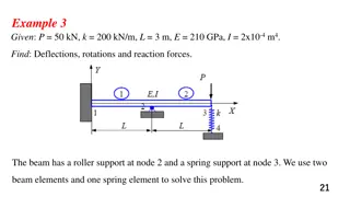
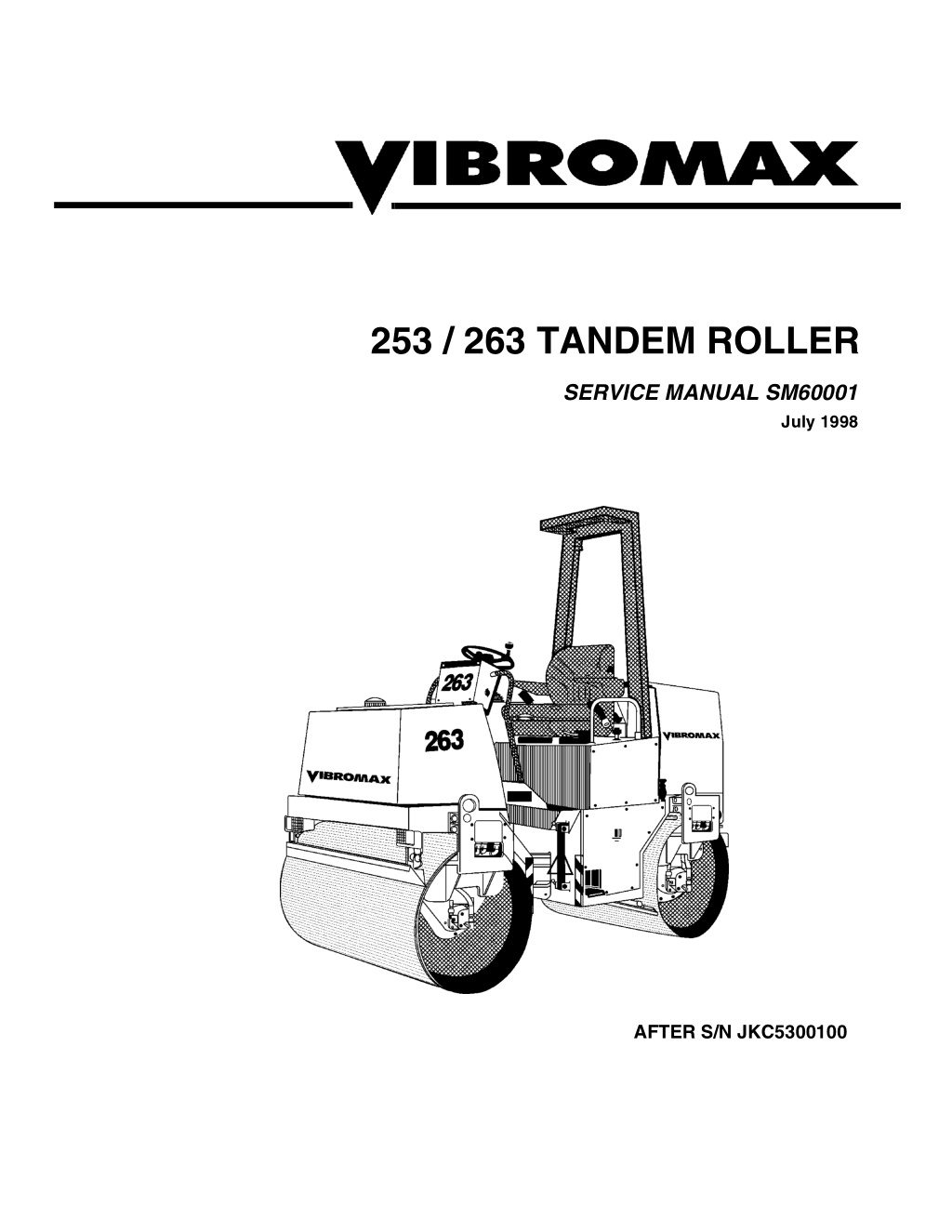
253 / 263 TANDEM ROLLER SERVICE MANUAL SM60001 July 1998 AFTER S/N JKC5300100
CALIFORNIA Proposition 65 Warning Diesel engine exhaust and some of its constituents are known to the State of California to cause cancer, birth defects, and other reproductive harm.
TABLE OF CONTENTS SECTION ONE GENERAL INFORMATION................................................. 9 MACHINE DESCRIPTION ......................................................................11 SERIAL NUMBERS....................................................................................... 13 IDENTIFYING MACHINE COMPONENTS................................................... 14 SAFETY, GENERAL ..............................................................................15 SPARK ARRESTER...................................................................................... 15 SAFETY, PERSONAL............................................................................ 15 SAFETY, MACHINE OPERATION .........................................................16 SAFETY, MAINTENANCE .......................................................................7 GENERAL INFORMATION.................................................................... 20 CLEANING.................................................................................................... 20 INSPECTION ................................................................................................20 BEARINGS ....................................................................................................20 NEEDLE BEARINGS .................................................................................... 20 GEARS...........................................................................................................20 OIL SEALS, O-RINGS, & GASKETS ............................................................20 SHAFTS........................................................................................................ 20 SERVICE PARTS ..........................................................................................20 LUBRICATION ..............................................................................................20 STANDARD TORQUE DATA ................................................................ 21 METRIC/USA CONVERSIONS.............................................................. 22 MACHINE SPECIFICATIONS................................................................ 23 FLUID SPECIFICATIONS ......................................................................25 DIESEL FUEL SPECIFICATION............................................................ 26 ENGINE OIL SPECIFICATION ..............................................................27 3
TABLE OF CONTENTS SECTION TWO ENGINE R&I ...................................................................... 29 ENGINE REMOVAL & INSTALLATION ................................................ 31 ENGINE REMOVAL ..................................................................................... 32 ENGINE OVERHAUL ................................................................................... 32 INSTALLATION............................................................................................ 33 SECTION THREE ELECTRICAL SYSTEMS.................................................. 35 ELECTRICAL INFORMATION............................................................... 36 RELAY LOCATION CHART.................................................................. 37 FUSE LOCATION CHART..................................................................... 37 UNDERSTANDING ELECTRICAL SCHEMATICS................................ 39 UNDERSTANDING RELAYS ................................................................. 41 VIBROMAX RELAYS.................................................................................... 43 EMERGENCY STOP CIRCUIT .............................................................. 45 STARTER/ CHARGING CIRCUIT.......................................................... 47 UNDERSTANDING BATTERIES ........................................................... 47 BATTERY DIAGNOSTICS ........................................................................... 48 UNDERSTANDING ALTERNATORS .................................................... 49 CHARGING SYSTEM DIAGNOSTICS ......................................................... 50 VOLTAGE CHECKS AT ALTERNATOR ..................................................... 51 SYSTEM LEAKAGE ..................................................................................... 51 CIRCUIT WIRING TEST................................................................................ 51 MEASURING ALTERNATOR OUTPUT........................................................ 52 UNDERSTANDING STARTERS .................................................................. 52 STARTER SOLENOID ................................................................................. 53 STARTER SYSTEM DIAGNOSTICS ..................................................... 53 SOLENOID CIRCUIT TEST ......................................................................... 53 4
https://www.ebooklibonline.com Hello dear friend! Thank you very much for reading. Enter the link into your browser. The full manual is available for immediate download. https://www.ebooklibonline.com
TABLE OF CONTENTS STARTER CIRCUIT WIRING TEST ............................................................. 54 STARTER MOTOR TEST..............................................................................55 NEUTRAL SWITCH CIRCUIT................................................................ 57 INSTRUMENTATION PANEL................................................................ 59 PARKING BRAKE CIRCUIT.................................................................. 61 VIBRATION CONTROL CIRCUIT.......................................................... 61 SPRINKLER CIRCUIT............................................................................ 63 ACCESSORY SOCKETS....................................................................... 63 LIGHTING CIRCUIT ............................................................................... 65 HAZARD/ DIRECTIONAL CIRCUIT....................................................... 65 BACK-UP ALARM ................................................................................. 66 WIRE HARNESS 7130/02015................................................................ 68 WIRE HARNESS 7130/02055................................................................ 71 ELECTRICAL SCHEMATICS ................................................................ 75 SECTION FOUR HYDRAULIC SYSTEMS.................................................... 81 PROPULSION SYSTEM ........................................................................ 83 PROPULSION SYSTEM DIAGNOSTICS .............................................. 83 INTERNAL LEAKAGE ...................................................................................83 PUMP SERVO CONTROL............................................................................ 84 VIBRATION SYSTEM ............................................................................ 87 VIBRATION SYSTEM DIAGNOSTICS ..................................................88 VIBRATION FREQUENCY ........................................................................... 88 STEERING SYSTEM.............................................................................. 91 STEERING SYSTEM DIAGNOSTICS.................................................... 91 HYDRAULIC RESERVOIR .....................................................................92 5
TABLE OF CONTENTS HYDRAULIC OIL FILTER ...................................................................... 93 HYDRAULIC OIL RESERVOIR ............................................................. 93 PARKING BRAKES............................................................................... 95 PARKING BRAKE DIAGNOSTICS ....................................................... 95 HYDRAULIC TEST PORTS................................................................... 96 HYDRAULIC SCHEMATIC.................................................................... 97 HYDRAULIC COMPONENTS ................................................................ 99 POCLAIN MC05 PROPULSION MOTOR ............................................ 100 SAUER/SUNDSTRAND SERIES 42 PROPULSION PUMP ................ 103 SECTION FIVE DRUM DRIVE .................................................................. 107 DRUM ASSEMBLY DRAWING ........................................................... 111 DRUM REMOVAL................................................................................ 115 DRIVE MOTOR REMOVAL .................................................................. 115 DRIVE MOTOR REPAIR...................................................................... 117 DRIVE MOTOR INSTALLATION......................................................... 117 DRUM DRIVE BEARING REMOVAL .................................................. 117 DRUM BEARING INSTALLATION ...................................................... 119 DRUM INSTALLATION ........................................................................ 119 SECTION SIX PARKING BRAKE SYSTEM ........................................... 121 PARK BRAKE TESTING ..................................................................... 123 BRAKE RELEASE FOR TOWING....................................................... 123 6
TABLE OF CONTENTS BRAKE REPAIRS ................................................................................ 125 BRAKE DISASSEMBLY ..............................................................................125 BRAKE ASSEMBLY ....................................................................................125 SECTION SEVEN VIBRATORY SYSTEM ....................................................127 VIBRATORY SHAFT REMOVAL......................................................... 133 VIBRATORY SHAFT INSTALLATION ................................................135 SECTION EIGHT STEERING SYSTEM .......................................................137 ARTICULATION JOINTS..................................................................... 139 ARTICULATION PARTS...................................................................... 140 HORIZONTAL PIVOT DISASSEMBLY....................................................... 143 STEERING PIVOT DISASSEMBLY............................................................ 143 STEERING PIVOT ASSEMBLY ..................................................................145 HORIZONTAL PIVOT INSTALLATION .......................................................145 STEERING CYLINDER ........................................................................ 146 SECTION NINE CHASSIS .........................................................................147 FRAME .................................................................................................149 PANELS ...............................................................................................150 OPERATOR PLATFORM..................................................................... 151 WATER TANK ......................................................................................152 WATER TANK COATING ....................................................................153 INERTOL POXITAR ....................................................................................153 7
TABLE OF CONTENTS ROLL OVER PROTECTIVE STRUCTURE (ROPS)............................ 154 ROPS MAINTENANCE .............................................................................. 155 ROPS DAMAGE......................................................................................... 155 ROPS BOLT TORQUE ............................................................................... 155 SUN ROOF ........................................................................................... 156 SECTION TEN ATTACHMENTS ............................................................. 157 WATER SPRINKLER SYSTEM ........................................................... 158 SPRINKLER FUNCTION............................................................................ 159 STORAGE PREPARATION ....................................................................... 159 DRUM SCRAPERS.............................................................................. 160 SCRAPER ADJUSTMENT ......................................................................... 161 LIGHT KIT 87130/20120 ...................................................................... 162 LIGHT KIT INSTALLATION ........................................................................ 163 SPOTLIGHT KIT 87130/20100 ............................................................ 164 SPOTLIGHT INSTALLATION ..................................................................... 165 BACK UP ALARM KIT 87130/20200 ................................................... 166 ALARM INSTALLATION ............................................................................. 167 8
SECTION ONE GENERAL INFORMATION CALIFORNIA Proposition 65 Warning Diesel engine exhaust and some of its constituents are known to the State of California to cause cancer, birth defects, and other reproductive harm. 9
NOTES 10
SECTION ONE GENERAL INFORMATION MACHINE DESCRIPTION The 253 Series vibratory roller is a new from the ground up machine, replacing the 252. The 253 is a 2.5 metric ton, tandem drum machine with articulated steering, hydrostatic drive and a hydraulically driven vibration system. The 253 has a 1000 mm (39 inch) drum width while the 263 is the 1200 mm (47 inch) drum width version. A Kubota D1403B, water cooled, three cylinder in-line diesel engine, mounted in the rear chassis, provides the power for the machine. The engine has a 29.0 Net Horse Power rating at 2600 RPM. A Sauer Sunstrand variable displacement hydrostatic pump, used for machine propulsion, is mounted to the flywheel end of the engine. It provides oil for the front and rear Poclain, fixed displacement, drum drive motors in a parallel path. The motors are located on the right hand side of the drums and are connected directly to the drum, without gear reduction. The vibration system consists of a fixed displacement gear pump mounted to the back of the propulsion pump. This gear pump drives the two gear motors (one on each drum, left hand side) in a series flow path, with options of vibration to the front drum only, rear drum only, both drums or neither drum. Oil from the vibration circuit passes through an air to oil cooler at the engine radiator. The exciter shafts and the drum bearings are oil lubricated, eliminating the need for grease zerks. 11
SECTION ONE GENERAL INFORMATION Front and rear parking brakes are provided Pressure testing of the hydraulic system on the 253/263. The drum brakes are inte- has been simplified by the location of a test gral to the drive motors. The brakes are station in the left side of the engine com- spring applied / hydraulically released and partment. Pressure testing of the drive, are controlled by a switch on the dash and charge, brake release, vibratory and steer- by an emergency stop switch on the right ing systems can be performed from one operators console. A tow valve, located location. under the operators seat, provides for brake release for towing purposes. The electrical system consists of the stan- dard starter, battery and charging circuit A steering pump, mounted to the back of along with optional lighting, hazard and the vibration pump, provides oil for the directional lights. The instrument panel steering control valve and a single steering includes switches for vibration, sprinklers, cylinder at the articulation joint. The joint is lights and brakes along with the standard maintenance free, providing 40 degrees of instrument cluster of warning lights and an articulation and 15 degrees of oscillation. hour meter. An emergency stop button is An articulation joint safety lock completes located right of the operator s seat, just to the steering system. the front of the lockable access panel for the fuse compartment. All electrical control The return oil flow from the vibratory circuit components are located behind a remov- and the steering circuit passes through a able panel on the right side of the operators 10 micron oil filter mounted in the top of the platform. hydraulic reservoir. A filter bypass and a pressure differential switch completes the A 53 gallon water tank is located on the filter circuit. The hydraulic reservoir is front chassis, providing water for the located below the operators platform on the asphalt sprinkler system. The tank s modu- left side of the rear chassis. The modular lar design allows for easy removal if neces- design of the reservoir makes it possible to sary. Fixed position scrapers on the front completely remove the reservoir if neces- and rear of each drum and a pressurized sary. sprinkler bar on each drum, complete the system. 12
SECTION ONE GENERAL INFORMATION SERIAL NUMBERS 1 2 3 4 5 6 7 8 Model / Serial Number Front Drum Drive Motor S/N Rear Drum Drive Motor S/N Steering Unit S/N Front Vibratory Motor S/N Rear Vibratory Motor S/N Hydraulic Pumps S/N Engine S/N 13
SECTION ONE GENERAL INFORMATION IDENTIFYING MACHINE COMPONENTS 1 2 3 4 5 6 7 8 9 Articulation joint Smooth drum Lifting eye Operator s stand Battery Hydraulic tank Engine Drum drive motor Rubber buffer Scraper 11 12 13 14 15 16 17 18 19 20 Spring loaded brake Water tank Fuel tank Air filter canister Water - oil cooler Roll over protection Vibration motor Steering cylinder Hydraulic pumps Sun roof 10 14
Suggest: If the above button click is invalid. Please download this document first, and then click the above link to download the complete manual. Thank you so much for reading
SECTION ONE GENERAL INFORMATION SAFETY, GENERAL The information in this manual does not replace any safety rules and laws used in your area. Before you operate this machine, learn the rules and laws for your area and make sure your machine has the correct equipment according to these rules and regulations. A fire can cause injury or death. Always have a fire extinguisher on the job site near the machine. Make sure the fire extin- guisher is serviced according to the manufacturer s instructions. Your safety and the safety of other persons in the work area are dependent on your correct operation of this machine. Foreign materials and loose objects on the steps, hand rails, and in the operator s compart- ment can cause accidents and injury. Keep the steps, hand rails, and opera- tor s compartment clear at all times. Know the location and function of all machine controls. Clear the area of other persons before you start the engine. Always use the seat belt when operating the machine. Make sure the buckle for the seat is fastened correctly. Check all controls in a safe area before you operate the machine. Understand the limits of the machine. Do not try to do too much too fast. Make sure cab win- dows are clean and unobstructed. Keep the machine under control at all times. Know and under- stand the arrangements for movement of trucks, machines, and persons on your job site. Understand and follow the instructions of flagmen, road signs, or signals. SPARK ARRESTER NOTE: Rules or laws in some areas can make it necessary for this machine to be equipped with a spark arrester or spark arrester muffler. Check the rules or laws in your area. Always wear the SAFETY, PERSONAL proper ear protection when operating this machine. Permanent hearing loss can result from extended exposure to loud noises. Loose clothing and jewelry can cause an accident. Do not wear loose clothing or jewelry that can catch on controls, etc. Do wear safety shoes, hard hat, heavy gloves, etc. when required for your protection. Check machine con- trols for proper operation prior to starting the machine. 15
https://www.ebooklibonline.com Hello dear friend! Thank you very much for reading. Enter the link into your browser. The full manual is available for immediate download. https://www.ebooklibonline.com