Caterpillar Cat 3512 VEHICULAR ENGINE (Prefix 51Y) Service Repair Manual Instant Download (51Y00001-00512)
Please open the website below to get the complete manualnn//

Download Presentation

Please find below an Image/Link to download the presentation.
The content on the website is provided AS IS for your information and personal use only. It may not be sold, licensed, or shared on other websites without obtaining consent from the author. Download presentation by click this link. If you encounter any issues during the download, it is possible that the publisher has removed the file from their server.
E N D
Presentation Transcript
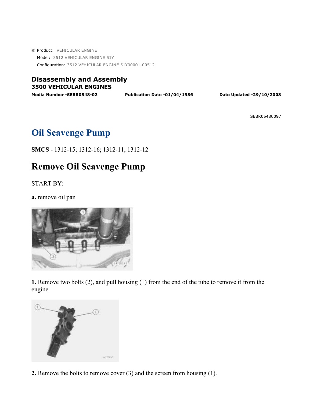
w 1/8(W) Product: VEHICULAR ENGINE Model: 3512 VEHICULAR ENGINE 51Y Configuration: 3512 VEHICULAR ENGINE 51Y00001-00512 Disassembly and Assembly 3500 VEHICULAR ENGINES Media Number -SEBR0548-02 Publication Date -01/04/1986 Date Updated -29/10/2008 SEBR05480097 Oil Scavenge Pump SMCS - 1312-15; 1312-16; 1312-11; 1312-12 Remove Oil Scavenge Pump START BY: a. remove oil pan 1. Remove two bolts (2), and pull housing (1) from the end of the tube to remove it from the engine. 2. Remove the bolts to remove cover (3) and the screen from housing (1). https://127.0.0.1/sisweb/sisweb/techdoc/techdoc_print_page.jsp?returnurl=/sisweb/siswe... 2022/5/8
w 2/8(W) 3. Remove bolts (6) to remove clips (7) and brackets (5) from tube (4). 4. Pull tube (4) from the scavenge pump, and remove tube (4) from the engine. Remove the O-ring seals from the tube. 5. Remove four bolts (9), and use two men to remove oil scavenge pump (8) from the engine. The weight of the pump is 32 kg (71 lb.). Install Oil Scavenge Pump 1. Use two men to put oil scavenge pump (1) in position, and install the bolts to hold the pump to the engine block. https://127.0.0.1/sisweb/sisweb/techdoc/techdoc_print_page.jsp?returnurl=/sisweb/siswe... 2022/5/8
w 3/8(W) 2. Install the O-ring seals on both ends of tube (2), and put clean engine oil on the seals. Put tube (2) in position in the scavenge pump. 3. Put clips (4) and brackets (3) in position on tube (2). Install bolts (5) to hold clips (4), brackets (3) and tube (2) in position on the engine block. 4. Clean and inspect screen (8), and make a replacement if necessary. Put screen (8) and cover (7) in position on housing (6). Install the bolts to hold these in position. 5. Put housing (6) in position on the end of tube (2), and install the bolts to hold the housing in position. END BY: a. install oil pan Disassemble Oil Scavenge Pump https://127.0.0.1/sisweb/sisweb/techdoc/techdoc_print_page.jsp?returnurl=/sisweb/siswe... 2022/5/8
https://www.ebooklibonline.com Hello dear friend! Thank you very much for reading. Enter the link into your browser. The full manual is available for immediate download. https://www.ebooklibonline.com
w 4/8(W) START BY: a. remove oil scavenge pump 1. Loosen bolt (1). Do not remove the bolt at this time. 2. Remove bolts (3) to remove gear (2) from the flange. 3. Use tooling (A) to loosen the flange to the drive shaft. Remove tooling (A), the bolt, washer and flange from the drive shaft. https://127.0.0.1/sisweb/sisweb/techdoc/techdoc_print_page.jsp?returnurl=/sisweb/siswe... 2022/5/8
w 5/8(W) 4. Put alignment marks on the pump body and cover (5) for correct assembly. Remove bolts (4) to remove cover (5) from the pump body. 5. If necessary, remove dowels (6) and bearings (7) from cover (5). 6. Remove drive shaft assembly (8) and idler shaft assembly (9) from the pump body. 7. If necessary, remove bearings (10) from the pump body. Assemble Oil Scavenge Pump https://127.0.0.1/sisweb/sisweb/techdoc/techdoc_print_page.jsp?returnurl=/sisweb/siswe... 2022/5/8
w 6/8(W) NOTE: Put clean engine oil on the shaft assemblies and bearings when the pump is assembled. 1. Use tool group (A) to install bearings (1) until they are 1.5 0.5 mm (.06 .02 in.) below the bottom of the gear bores in the pump body. Make sure the joints in the bearings are in the position shown. 2. Check the inside diameter of bearings (1) after they are installed. The inside diameter must be 31.837 0.070 mm (1.2534 .0028 in.). 3. If necessary, make a replacement of the gears on shaft assemblies (2) and (3). Heat the gears to a maximum temperature of 316 C (600 F), and install the gears on the shaft assemblies. The face of the gear on drive shaft assembly (2) must be 60.00 0.25 mm (2.362 .010 in.) from the threaded end of the shaft. The ends of idler shaft assembly (3) must be 34.0 0.5 mm (1.34 .02 in.) from the gear faces. 4. Install idler shaft assembly (3) and drive shaft assembly (2) in the pump body. https://127.0.0.1/sisweb/sisweb/techdoc/techdoc_print_page.jsp?returnurl=/sisweb/siswe... 2022/5/8
w 7/8(W) 5. Use tool group (A) to install bearings (5) in cover (6). Install bearings (5) with the joints in the position shown. Make sure the bearings are 1.5 0.5 mm (.06 .02 in.) below the surface of cover (6). 6. Check the inside diameter of bearings (5) after they are installed. The inside diameter must be 31.837 0.070 mm (1.2534 .0028 in.). 7. Install dowels (4) in cover (5) until they are 6.4 0.5 mm (.25 .02 in.) above the surface of cover (6) as shown. 8. Put cover (6) in position, and install the bolts to hold it to the pump body. 9. Put flange (7) in position on the drive shaft assembly. https://127.0.0.1/sisweb/sisweb/techdoc/techdoc_print_page.jsp?returnurl=/sisweb/siswe... 2022/5/8
w 8/8(W) 10. Install the washer and bolt (9). Tighten bolt (9) to a torque of 360 47 N m (266 34 lb.ft.). 11. Put gear (8) in position on the flange so the chamfer for the gear bore is next to the flange. Install the bolts that hold the gear to the flange. END BY: a. install oil scavenge pump https://127.0.0.1/sisweb/sisweb/techdoc/techdoc_print_page.jsp?returnurl=/sisweb/siswe... 2022/5/8
w 1/2(W) Product: VEHICULAR ENGINE Model: 3512 VEHICULAR ENGINE 51Y Configuration: 3512 VEHICULAR ENGINE 51Y00001-00512 Disassembly and Assembly 3500 VEHICULAR ENGINES Media Number -SEBR0548-02 Publication Date -01/04/1986 Date Updated -29/10/2008 SEBR05480098 Oil Sequence Valves SMCS - 1312-15; 1312-16; 1312-11; 1312-12 Remove And Install Oil Sequence Valves START BY: a. remove front drive housing b. remove flywheel housing 1. Remove cover (1) from the front of the cylinder block. 2. Remove plunger assembly (2) and spring (3) from the front of the cylinder block. https://127.0.0.1/sisweb/sisweb/techdoc/techdoc_print_page.jsp?returnurl=/sisweb/siswe... 2022/5/8
w 2/2(W) 3. Remove the gear assembly, idler gear and shaft from over cover (4) on the rear of the cylinder block. 4. Remove cover (4) from the rear of the cylinder block. 5. Remove plunger assembly (5) and spring (6) from the rear of the cylinder block. 6. Put clean engine oil on spring (6) and plunger assembly (5), and install them as shown in the rear of the cylinder block. 7. Install cover (4). Install the idler gear, shaft and gear assembly over cover (4) on the rear of the cylinder block. 8. Put clean engine oil on spring (3) and plunger assembly (2), and install them in the front of the cylinder block as shown. 9. Install cover (1) to hold the plunger assembly and spring in position. END BY: a. install flywheel housing b. install front drive housing https://127.0.0.1/sisweb/sisweb/techdoc/techdoc_print_page.jsp?returnurl=/sisweb/siswe... 2022/5/8
w 1/8(W) Product: VEHICULAR ENGINE Model: 3512 VEHICULAR ENGINE 51Y Configuration: 3512 VEHICULAR ENGINE 51Y00001-00512 Disassembly and Assembly 3500 VEHICULAR ENGINES Media Number -SEBR0548-02 Publication Date -01/04/1986 Date Updated -29/10/2008 SEBR05480099 Oil Cooler SMCS - 1378-15; 1378-16; 1378-11; 1378-12 Remove Oil Cooler 1. Drain the coolant from the cooling system. 2. Drain the oil from the oil cooler. 3. Disconnect fuel lines (1) and (2) from the fuel transfer pump and the fuel filter base. Remove the fuel lines from the engine. 4. Disconnect elbow (3) from the oil cooler. 5. Remove bolts (4) that hold the oil cooler bonnet to the bracket. https://127.0.0.1/sisweb/sisweb/techdoc/techdoc_print_page.jsp?returnurl=/sisweb/siswe... 2022/5/8
w 2/8(W) 6. Remove elbow (6) and tube (5) as a unit from oil cooler bonnet (7). 7. Fasten a hoist to the oil cooler, and remove bolts (8) from bonnet (7). Pull the oil cooler from water line (10) and oil line (9). 8. Remove the oil cooler from the engine. The weight of the oil cooler for 3512 Engines is 66 kg (145 lb.). The weight of the oil cooler for 3516 Engines is 78 kg (172 lb.). Install Oil Cooler 1. Make sure the O-ring seals for tubes (2) and (4) are in position. Put clean engine oil on the seals. 2. Fasten a hoist, and put the oil cooler in position on tube (4) and elbow (3). Install the bolts to hold oil cooler bonnets (1) and (5) to the engine. https://127.0.0.1/sisweb/sisweb/techdoc/techdoc_print_page.jsp?returnurl=/sisweb/siswe... 2022/5/8
w 3/8(W) 3. Put clean engine oil on the O-ring seal on tube (7). Put tube (7) and elbow (6) in position in bonnet (1). Make sure the gasket is in position, and install the bolts to hold elbow (6) to the engine. 4. Put clean engine oil on the O-ring seal, and connect elbow (8) to the oil cooler. 5. Put fuel lines (9) and (10) in position on the engine. Connect the fuel lines to the fuel filter base and the fuel transfer pump. 6. Fill the engine with oil to the correct level. See the Maintenance Guide. 7. Fill the cooling system with coolant to the correct level. See the Maintenance Guide. Disassemble Oil Cooler START BY: a. remove oil cooler https://127.0.0.1/sisweb/sisweb/techdoc/techdoc_print_page.jsp?returnurl=/sisweb/siswe... 2022/5/8
w 4/8(W) 1. Remove the bolts from elbow (1). Remove elbow (1) and tube (2) as a unit from the oil cooler. 2. Remove tube (2) from elbow (1). Remove the O-ring seals from tube (2) and elbow (1). 3. Put alignment marks on bonnet (3) and core assembly (4) for correct alignment at assembly. Remove bonnet (3) from cover assembly (4). 4. Remove flange (7) and tube (6) as a unit from bonnet (5). Remove the O-ring seals from tube (6). https://127.0.0.1/sisweb/sisweb/techdoc/techdoc_print_page.jsp?returnurl=/sisweb/siswe... 2022/5/8
w 5/8(W) 5. Remove the bolts, and remove elbow (8) from core assembly (4). 6. Remove the bolts, and remove cover (9) from elbow (8). Remove the O-ring seal from cover (9). 7. Remove spring (10) and plunger (11) from elbow (8). 8. Remove the bolts and cover (13) from elbow (8). Remove O-ring seals (12) from elbow (8). https://127.0.0.1/sisweb/sisweb/techdoc/techdoc_print_page.jsp?returnurl=/sisweb/siswe... 2022/5/8
w 6/8(W) 9. Put alignment marks on bonnet (5) and core assembly (4) for correct alignment at assembly. Remove bonnet (5) from core assembly (4). Assemble Oil Cooler 1. Make sure the tubes in core assembly (1) are clean and free of dirt and foreign material. 2. Put the gasket and bonnet (2) in position on core assembly (1), and install the bolts that hold it. 3. Install O-ring seals (4) on elbow (3), and put clean engine oil on the seals. Install cover (5) on elbow (3). https://127.0.0.1/sisweb/sisweb/techdoc/techdoc_print_page.jsp?returnurl=/sisweb/siswe... 2022/5/8
w 7/8(W) 4. Put plunger (7) and spring (8) in position in elbow (3). Install the O-ring seal in cover (6), and put clean engine oil on it. Install cover (6) on elbow (3). 5. Put elbow (3) in position on the core assembly, and install the bolts that hold it. 6. Install the O-ring seals on tube (9), and put clean engine oil on the seals. Install tube (9) and flange (10) as a unit in bonnet (2). 7. Put the gasket and bonnet (11) in position on core assembly (1), and install the bolts that hold it. https://127.0.0.1/sisweb/sisweb/techdoc/techdoc_print_page.jsp?returnurl=/sisweb/siswe... 2022/5/8
Suggest: For more complete manuals. Please go to the home page. https://www.ebooklibonline.com If the above button click is invalid. Please download this document first, and then click the above link to download the complete manual. Thank you so much for reading
w 8/8(W) 8. Install the O-ring seals on tube (13), and put clean engine oil on the seals. Install tube (13) in elbow (12). 9. Install the O-ring seal on elbow (12), and put clean engine oil on it. Put elbow (12) and tube (13) as a unit in position, and install the bolts in elbow (12) to hold the elbow and the tube in position. END BY: a. install oil cooler https://127.0.0.1/sisweb/sisweb/techdoc/techdoc_print_page.jsp?returnurl=/sisweb/siswe... 2022/5/8
w 1/3(W) Product: VEHICULAR ENGINE Model: 3512 VEHICULAR ENGINE 51Y Configuration: 3512 VEHICULAR ENGINE 51Y00001-00512 Disassembly and Assembly 3500 VEHICULAR ENGINES Media Number -SEBR0548-02 Publication Date -01/04/1986 Date Updated -29/10/2008 SEBR05480100 Trunnion SMCS - 1153-10 Remove And Install Trunnion START BY: a. remove crankshaft pulley and vibration damper b. remove oil pan 1. Drain the coolant from the cooling system. 2. Disconnect the water pump inlet from the radiator. 3. Remove the bolts that hold trunnion (2) to the frame of the vehicle. https://127.0.0.1/sisweb/sisweb/techdoc/techdoc_print_page.jsp?returnurl=/sisweb/siswe... 2022/5/8
https://www.ebooklibonline.com Hello dear friend! Thank you very much for reading. Enter the link into your browser. The full manual is available for immediate download. https://www.ebooklibonline.com