Understanding Mean Effective Pressure in Internal Combustion Engines
ME 433
Internal Combustion Engines
Professor:
Dr. Dan Cordon (AKA Dr. Dan)
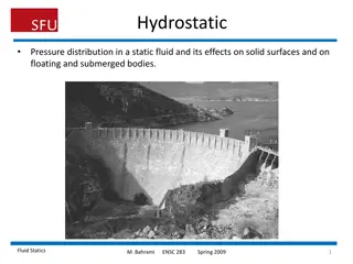
Mean Effective Pressure
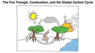
The name implies that it is the average pressure. That is exactly what it is. If you
were to look at the net work of the actual cycle, then replace that with a power
stroke at constant pressure that delivered the same net work, that pressure
would be the MEP.
2
S
a
m
e
W
o
r
k
Mean Effective Pressure
N
o
t
e
:
M
E
P
i
s
r
e
l
a
t
i
v
e
l
y
c
o
n
s
i
s
t
e
n
t
f
o
r
g
i
v
e
n
e
n
g
i
n
e
t
y
p
e
s
,
r
e
g
a
r
d
l
e
s
s
o
f
d
i
s
p
l
a
c
e
m
e
n
t
.
T
h
i
s
m
e
a
n
s
t
h
a
t
i
t
i
s
f
a
i
r
l
y
e
a
s
y
t
o
p
r
e
d
i
c
t
T
o
r
q
u
e
o
u
t
p
u
t
i
f
y
o
u
k
n
o
w
t
h
e
e
n
g
i
n
e
t
y
p
e
a
n
d
t
h
e
d
i
s
p
l
a
c
e
d
v
o
l
u
m
e
.
3
S
I
E
n
g
i
n
e
C
I
E
n
g
i
n
e
P
e
a
k
M
E
P
N
.
A
.
~
8
5
0
-
1
2
0
0
k
P
a
N
.
A
.
~
7
0
0
-
9
0
0
k
P
a
F.I. ~1200-1700 kPa
F.I. ~1400-2000 kPa
I
n
t
a
k
e
a
n
d
E
x
h
a
u
s
t
S
t
r
o
k
e
s
–
I
d
e
a
l
C
y
c
l
e
s
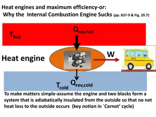
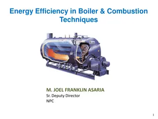
In the ideal four-stroke cycle the exhaust process is modeled as
constant volume heat extraction and does not consider the actual gas flow.
At WOT the exhaust and intake processes
are often shown as a constant pressure
processes, e.g., 5
6 and 6
1 where
states 1 and 5 are the same.
Process 5-6 indicates a decrease in
specific volume which is incorrect since
as the cylinder volume decreases so does
the mass
specific volume remains the
same!
This inconsistency is a byproduct of modeling
an open system problem with a closed
system equations.
P
r
e
s
s
u
r
e
,
P
S
p
e
c
i
f
i
c
v
o
l
u
m
e
,
v
E
V
c
l
o
s
e
s
I
V
o
p
e
n
s
I
V
c
l
o
s
e
s
E
V
o
p
e
n
s
U
n
t
h
r
o
t
t
l
e
d
:
P
i
=
P
e
=
1
a
t
m
T
h
r
o
t
t
l
e
d
:
P
i
<
P
e
S
u
p
e
r
c
h
a
r
g
e
d
:
P
i
>
P
e
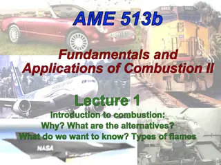
In an ideal four-stroke Otto cycle engine
valves operate instantaneously, and both exhaust and intake
process are adiabatic and constant pressure.
E
V
c
l
o
s
e
s
I
V
o
p
e
n
s
E
V
c
l
o
s
e
s
I
V
o
p
e
n
s
6
’
E
V
o
p
e
n
s
I
V
c
l
o
s
e
s
(
s
t
a
t
e
1
)
E
V
o
p
e
n
s
I
V
c
l
o
s
e
s
I
n
t
a
k
e
a
n
d
E
x
h
a
u
s
t
S
t
r
o
k
e
s
–
I
d
e
a
l
C
y
c
l
e
s
R
e
s
u
l
t
:
N
o
P
u
m
p
i
n
g
L
o
s
s
R
e
s
u
l
t
:
N
e
t
P
u
m
p
i
n
g
L
o
s
s
1
E
V
c
l
o
s
e
s
I
V
o
p
e
n
s
6
’
E
V
o
p
e
n
s
I
V
c
l
o
s
e
s
R
e
s
u
l
t
:
N
e
t
P
u
m
p
i
n
g
G
a
i
n
B
l
o
w
d
o
w
n
–
A
t
t
h
e
e
n
d
o
f
t
h
e
p
o
w
e
r
s
t
r
o
k
e
w
h
e
n
t
h
e
e
x
h
a
u
s
t
v
a
l
v
e
o
p
e
n
s
the cylinder pressure is much higher than the exhaust manifold pressure
which is typically ~1 atm (P
4
> P
e
), so the cylinder gas flows out through the
exhaust valve and the pressure rapidly drops to P
e
.
D
i
s
p
l
a
c
e
m
e
n
t
–
R
e
m
a
i
n
i
n
g
g
a
s
i
s
p
u
s
h
e
d
o
u
t
o
f
t
h
e
c
y
l
i
n
d
e
r
b
y
t
h
e
p
i
s
t
o
n
moving to TDC.
A
c
t
u
a
l
E
x
h
a
u
s
t
S
t
r
o
k
e
s
S
t
a
t
e
4
(
B
C
)
S
t
a
t
e
5
(
B
C
)
S
t
a
t
e
6
(
T
C
)
P
i
T
i
P
e
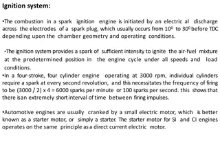
The actual exhaust process consists of two phases:
Blowdown
Displacement
B
l
o
w
d
o
w
n
D
i
s
p
l
a
c
e
m
e
n
t
Products
During the blowdown (if we neglect heat transfer) the gas remaining in
the cylinder undergoes an isentropic expansion process (circled in red)
•
State 5 at the end of blowdown is a fictitious state corresponding to no actual piston
location.
•
The p*dV work from State 4 to fictitious State 5 ends up equaling the flow work required
to move the gas out of the cylinder.
•
You can find T
5
with the following relationships:
B
l
o
w
d
o
w
n
5
(
O
t
t
o
/
D
i
e
s
e
l
)
D
i
s
p
l
a
c
e
m
e
n
t
After Blowdown the cylinder (still assumed to be at V
BDC
) is still full of
exhaust products.
P
4
(before Blowdown) will depend on State 3
•
For Otto Cycle engine, what was throttle position, and peak pressure
•
For Diesel Cycle engine, how much fuel was added, and Cut-Off Ratio
For an engine under high load, as much as 75% of the trapped mass in
the cycle (exhaust products) exit during Blowdown. At very light loads
sometimes as little as 15% of the trapped mass leave during blowdown.
The exhaust gasses remaining at BDC are pushed out by the piston
displacement (exhaust stroke). The work required for this can be
approximated by:
N
o
t
e
:
V
i
s
t
o
t
a
l
v
o
l
u
m
e
,
n
o
t
s
p
e
c
i
f
i
c
v
o
l
u
m
e
R
e
s
i
d
u
a
l
G
a
s
The gas remaining in the cylinder when the piston reaches TC is called
r
e
s
i
d
u
a
l
g
a
s
w
h
i
c
h
m
i
x
e
s
w
i
t
h
i
n
t
a
k
e
g
a
s
(
f
u
e
l
-
a
i
r
f
o
r
S
I
a
n
d
a
i
r
f
o
r
C
I
)
The residual gas temperature T
6
is equal to T
5
T
h
e
R
e
s
i
d
u
a
l
g
a
s
f
r
a
c
t
i
o
n
f
i
s
d
e
f
i
n
e
d
a
s
t
h
e
r
a
t
i
o
o
f
t
h
e
m
a
s
s
o
f
r
e
s
i
d
u
a
l
g
a
s
t
o
t
h
e
m
a
s
s
o
f
t
h
e
f
u
e
l
-
a
i
r
a
t
t
h
e
s
t
a
r
t
o
f
t
h
e
c
y
c
l
e
.
(
A
s
s
u
m
e
i
d
e
a
l
g
a
s
P
v
=
R
T
)
Typically values of
f
are in the range 3% to 12%, depending on
load, and will typically be lower in Diesels (larger CR)
10
When the intake valve opens the fresh gas (mass of
m
i
) mixes with the
hotter residual gas (mass of
m
R
) so the gas temperature at the end of the
intake stroke T
1
will be greater than the inlet temperature T
i
.
Applying conservation of mass:
I
n
t
a
k
e
S
t
r
o
k
e
6
1
Applying conservation of energy (open system):
T
i
11
Recall m
6
= m
1
*f
and assuming ideal gas
P
6
v
6
= RT
6
and
h = c
p
T
In terms of inlet and exhaust conditions
P
1
= P
i
, P
6
= P
e
, T
6
= T
e
I
n
t
a
k
e
G
a
s
T
e
m
p
e
r
a
t
u
r
e
(
T
1
)
12
V
a
l
v
e
O
v
e
r
l
a
p
In real engines valves don’t open and close instantaneously.
In order to ensure that the valve is fully open during a stroke for volumetric
efficiency, the valves are open for longer than 180
o
.
The exhaust valve opens before TC and closes after BC and the intake
valve opens before TC and closes after BC.
A
t
T
C
t
h
e
r
e
i
s
a
p
e
r
i
o
d
o
f
v
a
l
v
e
o
v
e
r
l
a
p
w
h
e
r
e
b
o
t
h
t
h
e
i
n
t
a
k
e
a
n
d
e
x
h
a
u
s
t
v
a
l
v
e
s
a
r
e
o
p
e
n
.
13
When the intake valve opens the cylinder pressure is at P
e
Part throttle
(P
i
< P
e
): residual gas flows into the intake port. During intake
stroke the residual gas is first returned to the cylinder then fresh gas is
introduced. Residual gas reduces part load performance.
WOT
(P
i
= P
e
): some fresh gas can flow out the exhaust valve reducing
performance and increasing emissions.
Supercharged
(P
i
> P
e
): fresh gas can flow out the exhaust valve
V
a
l
v
e
o
v
e
r
l
a
p
P
i
Throttled
P
i
< P
e
P
i
Supercharged
P
i
> P
e
P
e
P
e
14
V
a
l
v
e
T
i
m
i
n
g
Conventional engines operate at low rpms, with idle and part load important
High performance engines operate at high rpms at WOT, with power and
volumetric efficiency important
A
t high engine speeds less time available for fresh gas intake so need more
crank angles to get high volumetric efficiency
large valve overlap
At low engine speed and part throttle valve overlap is minimized by reducing
the angle duration for valves staying open.
V
o
l
u
m
e
t
r
i
c
E
f
f
i
c
i
e
n
c
y
Volumetric efficiency is affected by :
•
Fuel evaporation
•
Mixture temperature
•
Pressure drop in the intake system
•
Gas dynamic effects
Note:
piston speed is proportional
to air flow velocity
Where:
m
a
= mass of air trapped at start of cycle
ρ
a,o
= density of ambient air
V
d
= displaced volume
16
F
a
c
t
o
r
s
a
f
f
e
c
t
i
n
g
v
a
s
a
f
u
n
c
t
i
o
n
o
f
s
p
e
e
d
Fuel vapour pressure
17
V
a
r
i
a
b
l
e
V
a
l
v
e
T
i
m
i
n
g
Camshaft Profiles
https://youtu.be/BQ05PDVApJw?si=bhKq1SziVQNnU-I7&t=94
The Honda VTEC and Mitsubishi MIVEC engines have two camshaft
profiles on each cam lobe.
•
The low-speed cam profile has little exhaust-intake overlap
•
The high-speed cam profile has more overlap, longer duration, and a
higher overall lift
•
The high-speed cam profile is either the same, or a larger radius than
the low-speed cam profile.
•
At a set condition (usually engine speed) a hydraulic actuator allows
the valves to be operated by the high-speed cam profile rather than
the low-speed profile.
•
https://youtu.be/tSCuRXnfLuI?si=-v_XTm_c93DrPKZ3&t=159
•
When *should* the switch from low-speed to high-speed occur?
•
https://youtu.be/lcohmc-yB5A?si=fz-uFBpSB47cw1pg&t=15
18
V
a
r
i
a
b
l
e
V
a
l
v
e
T
i
m
i
n
g
–
C
a
m
P
h
a
s
e
r
s
Many engines designed after the mid 2000’s. use cam phasing as a way
to increase volumetric efficiency across the operating speed of the
engine.
https://youtu.be/Qr7J6Rl4P24?si=PZq0R26QzQo8lxU_&t=15
•
Phase only represents a change in the camshaft timing relative to the
crankshaft.
•
The camshaft profile does not change, but the camshaft can be either
advanced or retarded by several degrees.
•
The phase change takes time (100-250 ms) to occur, so it is not able
to advance, then retard the profile during a single cycle.
•
Advancing cam timing will close the valves sooner, and is usually
better for low-speed operation.
•
Retarding cam timing will close the valves later, which is usually better
for high-speed operation.
•
On DOHC (dual overhead camshaft) engines you can alter phase of
the intake and exhaust cam separately.
19
V
a
r
i
a
b
l
e
V
a
l
v
e
T
i
m
i
n
g
–
D
i
s
c
r
e
t
e
V
a
l
v
e
C
o
n
t
r
o
l
If you don’t constrain yourself to metal camshafts as a means of opening
and closing valves, what are some ideas you could do?
•
Four-stroke, six-stroke, 8-stroke diesel engines.
•
Atkinson cycle engine
•
Throttless engine (minimize parasitic pumping loss)
Challenges with discrete valve control
•
PTVC (piston to valve clearance)
•
Energy requirements
•
Reliability of components
•
Natural frequency (resonance)
•
Longevity of components
•
Cost of components
20
V
a
l
v
e
l
e
s
s
E
n
g
i
n
e
s
?
Most four-stroke engines have intake and exhaust valves to control the
gas exchange process. But it doesn’t *have* to be that way.
•
Coates Spherical Rotary Valve
•
Detroit Diesel externally
scavenged two-stroke engine
•
Dr. Dan’s uniflow DI two-stroke
•
Koenigsegg Freevalve
•
The Wankel (rotary) engine
Mean Effective Pressure (MEP) is a crucial parameter in internal combustion engines, representing the average pressure exerted on the piston during the power stroke. MEP is relatively consistent for specific engine types, making it a useful predictor of torque output based on engine type and displacement volume. The ideal and actual intake and exhaust strokes in a four-stroke cycle play a significant role in MEP calculations, impacting engine performance and efficiency.
- Internal Combustion Engines
- Mean Effective Pressure
- Torque Output
- Engine Types
- Intake and Exhaust Strokes

Download Presentation

Please find below an Image/Link to download the presentation.
The content on the website is provided AS IS for your information and personal use only. It may not be sold, licensed, or shared on other websites without obtaining consent from the author. Download presentation by click this link. If you encounter any issues during the download, it is possible that the publisher has removed the file from their server.
E N D
Presentation Transcript
ME 433 Internal Combustion Engines Professor: Dr. Dan Cordon (AKA Dr. Dan)
Mean Effective Pressure The name implies that it is the average pressure. That is exactly what it is. If you were to look at the net work of the actual cycle, then replace that with a power stroke at constant pressure that delivered the same net work, that pressure would be the MEP. Same Work 2
Mean Effective Pressure net work for one cycle displacement volume = mep ??? =?????? =2? ?????? ?? ?????? ?????? SI Engine N.A. ~850-1200 kPa F.I. ~1200-1700 kPa CI Engine N.A. ~700-900 kPa F.I. ~1400-2000 kPa Peak MEP Note: MEP is relatively consistent for given engine types, regardless of displacement. This means that it is fairly easy to predict Torque output if you know the engine type and the displaced volume. 3
Intake and Exhaust Strokes Ideal Cycles In the ideal four-stroke cycle the exhaust process is modeled as constant volume heat extraction and does not consider the actual gas flow. At WOT the exhaust and intake processes are often shown as a constant pressure processes, e.g., 5 6 and 6 1 where states 1 and 5 are the same. Pressure, P Process 5-6 indicates a decrease in specific volume which is incorrect since as the cylinder volume decreases so does the mass specific volume remains the same! EV closes IV opens IV closes EV opens This inconsistency is a byproduct of modeling an open system problem with a closed system equations. Specific volume, v
Intake and Exhaust Strokes Ideal Cycles In an ideal four-stroke Otto cycle engine valves operate instantaneously, and both exhaust and intake process are adiabatic and constant pressure. EV opens Unthrottled: Pi = Pe = 1 atm Result: No Pumping Loss IV closes (state1) EV closes IV opens Throttled: Pi < Pe Result: Net Pumping Loss EV opens EV closes IV closes 6 IV opens Supercharged: Pi > Pe Result: Net Pumping Gain EV opens IV opens 6 1 IV closes EV closes
Actual Exhaust Strokes The actual exhaust process consists of two phases: Blowdown Displacement Pe Pi Ti Products State 4 (BC) State 5 (BC) State 6 (TC) Blowdown Displacement Blowdown At the end of the power stroke when the exhaust valve opens the cylinder pressure is much higher than the exhaust manifold pressure which is typically ~1 atm (P4 > Pe), so the cylinder gas flows out through the exhaust valve and the pressure rapidly drops to Pe. Displacement Remaining gas is pushed out of the cylinder by the piston moving to TDC.
Blowdown During the blowdown (if we neglect heat transfer) the gas remaining in the cylinder undergoes an isentropic expansion process (circled in red) Blowdown Displacement 5 5 (Otto/Diesel) BC TC State 5 at the end of blowdown is a fictitious state corresponding to no actual piston location. The p*dV work from State 4 to fictitious State 5 ends up equaling the flow work required to move the gas out of the cylinder. You can find T5 with the following relationships: ? 1? ? 1? ?5 ?4 ?? ?4 ?5= ?4 = ?4 ?5= ??
Displacement After Blowdown the cylinder (still assumed to be at VBDC) is still full of exhaust products. P4 (before Blowdown) will depend on State 3 For Otto Cycle engine, what was throttle position, and peak pressure For Diesel Cycle engine, how much fuel was added, and Cut-Off Ratio For an engine under high load, as much as 75% of the trapped mass in the cycle (exhaust products) exit during Blowdown. At very light loads sometimes as little as 15% of the trapped mass leave during blowdown. The exhaust gasses remaining at BDC are pushed out by the piston displacement (exhaust stroke). The work required for this can be approximated by: Wexh= pe(VBDC VTDC) Note: V is total volume, not specific volume
Residual Gas The gas remaining in the cylinder when the piston reaches TC is called residual gas which mixes with intake gas (fuel-air for SI and air for CI) The residual gas temperature T6 is equal to T5 The Residual gas fraction f is defined as the ratio of the mass of residual gas to the mass of the fuel-air at the start of the cycle. (Assume ideal gas Pv = RT) v V m m 1 r 1 r 1 r m m P P v T T 6 6 6 6 6 6 4 4 4 = = = = = = f V v v T P T P 1 4 4 4 6 6 4 5 4 1 k 1 1 k T P 1 1 P P 5 5 k k = since = = 5 e f T P CR P CR P 4 4 4 4 Typically values of f are in the range 3% to 12%, depending on load, and will typically be lower in Diesels (larger CR)
Intake Stroke 6 1 When the intake valve opens the fresh gas (mass of mi) mixes with the hotter residual gas (mass of mR) so the gas temperature at the end of the intake stroke T1 will be greater than the inlet temperature Ti. Applying conservation of mass: Ti = = m m m m m 1 1 6 i R Applying conservation of energy (open system): u = + U U Q W m h 1 6 m 6 1 6 V 1 i i = m + ( h ) m u P V m h 1 1 h 6 6 1 6 i i i ( ) ( ) ( ) = + ( ) m P v P v P V V m m h 1 1 1 1 6 6 6 6 1 6 1 6 i i m m ( ) = + + 6 1 1 h h h P P v 1 6 1 6 6 i m m 1 6 10
Intake Gas Temperature (T1) Recall m6 = m1*f and assuming ideal gas P6v6 = RT6 and h = cpT 1 P ( ) P = + 1 1 h f h fh fRT 1 6 6 i P 6 1 1 k ( ) = + 1 1 1 T f T fT 1 6 i P k 6 In terms of inlet and exhaust conditions P1 = Pi , P6 = Pe , T6 = Te 1 1 P k ( ) = + 1 1 i T f T fT 1 i e P k e 11
Valve Overlap In real engines valves don t open and close instantaneously. In order to ensure that the valve is fully open during a stroke for volumetric efficiency, the valves are open for longer than 180o. The exhaust valve opens before TC and closes after BC and the intake valve opens before TC and closes after BC. At TC there is a period of valve overlap where both the intake and exhaust valves are open. 12
Valve overlap When the intake valve opens the cylinder pressure is at Pe Part throttle (Pi < Pe): residual gas flows into the intake port. During intake stroke the residual gas is first returned to the cylinder then fresh gas is introduced. Residual gas reduces part load performance. WOT (Pi = Pe): some fresh gas can flow out the exhaust valve reducing performance and increasing emissions. Supercharged (Pi > Pe): fresh gas can flow out the exhaust valve Pi Pe Pe Pi Supercharged Pi > Pe Throttled Pi < Pe 13
Valve Timing Conventional engines operate at low rpms, with idle and part load important High performance engines operate at high rpms at WOT, with power and volumetric efficiency important At high engine speeds less time available for fresh gas intake so need more crank angles to get high volumetric efficiency large valve overlap At low engine speed and part throttle valve overlap is minimized by reducing the angle duration for valves staying open. 14
Volumetric Efficiency m = a V v , a o d Where: ma = mass of air trapped at start of cycle a,o = density of ambient air Vd = displaced volume Volumetric efficiency is affected by : Fuel evaporation Mixture temperature Pressure drop in the intake system Gas dynamic effects Note: piston speed is proportional to air flow velocity
Factors affecting v as a function of speed Fuel vapour pressure 16
Variable Valve Timing Camshaft Profiles https://youtu.be/BQ05PDVApJw?si=bhKq1SziVQNnU-I7&t=94 The Honda VTEC and Mitsubishi MIVEC engines have two camshaft profiles on each cam lobe. The low-speed cam profile has little exhaust-intake overlap The high-speed cam profile has more overlap, longer duration, and a higher overall lift The high-speed cam profile is either the same, or a larger radius than the low-speed cam profile. At a set condition (usually engine speed) a hydraulic actuator allows the valves to be operated by the high-speed cam profile rather than the low-speed profile. https://youtu.be/tSCuRXnfLuI?si=-v_XTm_c93DrPKZ3&t=159 When *should* the switch from low-speed to high-speed occur? https://youtu.be/lcohmc-yB5A?si=fz-uFBpSB47cw1pg&t=15 17
Variable Valve Timing Cam Phasers Many engines designed after the mid 2000 s. use cam phasing as a way to increase volumetric efficiency across the operating speed of the engine. https://youtu.be/Qr7J6Rl4P24?si=PZq0R26QzQo8lxU_&t=15 Phase only represents a change in the camshaft timing relative to the crankshaft. The camshaft profile does not change, but the camshaft can be either advanced or retarded by several degrees. The phase change takes time (100-250 ms) to occur, so it is not able to advance, then retard the profile during a single cycle. Advancing cam timing will close the valves sooner, and is usually better for low-speed operation. Retarding cam timing will close the valves later, which is usually better for high-speed operation. On DOHC (dual overhead camshaft) engines you can alter phase of the intake and exhaust cam separately. 18
Variable Valve Timing Discrete Valve Control If you don t constrain yourself to metal camshafts as a means of opening and closing valves, what are some ideas you could do? Four-stroke, six-stroke, 8-stroke diesel engines. Atkinson cycle engine Throttless engine (minimize parasitic pumping loss) Challenges with discrete valve control PTVC (piston to valve clearance) Energy requirements Reliability of components Natural frequency (resonance) Longevity of components Cost of components 19
Valveless Engines? Most four-stroke engines have intake and exhaust valves to control the gas exchange process. But it doesn t *have* to be that way. Coates Spherical Rotary Valve Detroit Diesel externally scavenged two-stroke engine Dr. Dan s uniflow DI two-stroke Koenigsegg Freevalve The Wankel (rotary) engine 20


")