Understanding Changes in IBIS 6.2 Editorial Resolutions
Explore key updates in the IBIS 6.2 Editorial Resolutions, including new definitions, GND usage clarification, DUT vs. DIA descriptions, and model name guidelines. Learn about the distinctions between Device Under Test (DUT) and Device In Action (DIA) in IBIS files. Discover how IBIS files describe device behaviors and buffer data, aiding in EDA simulations. Gain insights into reference node clarification and reserved model names for pins in component descriptions.

Download Presentation

Please find below an Image/Link to download the presentation.
The content on the website is provided AS IS for your information and personal use only. It may not be sold, licensed, or shared on other websites without obtaining consent from the author. Download presentation by click this link. If you encounter any issues during the download, it is possible that the publisher has removed the file from their server.
E N D
Presentation Transcript
IBIS 6.2 Editorial Resolutions rev 2 15 Apr 2016 NOTE: IBIS page numbers refer to ver6_1.pdf 10/6/2024 1
BIRD Process Most edits can be contained in a single BIRD with the edited IBIS 6.2 as an attachment. We will need to maintain at least a general summary of changes made for the BIRD text and for the specification revision history. Some technical changes may require separately written BIRDs, particularly if the parser is affected. The editorial BIRD will incorporate these changes already. BIRDs will be submitted directly from this task group. 4/1/2016 2
New Definitions Port - ? Node - ? Terminal - ? Reference Terminal - ? Voltage - ? Power - ? Ground - ? Rail - ? 4/1/2016 3
GND Used Three Ways Which do we allow? Reserved [Pin] model_name Node name Bus label 4/1/2016 4
DUT vs DIA IBIS must describe a Device Under Test IBIS may describe the Device In Action Vinl/Vinh reference locations would be shown AMI describes DIA 10/6/2024 5
DUT vs DIA, page 4 Add text: IBIS files do not define buffer models . Instead, keywords and subparameters in IBIS files describe device behaviors in terms of data sets, to be used in combination with model equations and assumptions defined within EDA simulation tools. These data sets are generally assumed to have been collected under static conditions using a test fixture. In other words, IBIS buffer data generally describes a device under test (DUT), where the actual modeling of the collected data is performed by the EDA simulator. 4/21/2016 6
Define Reserved Model Names, Page 9 POWER The terminal for this pin is connected to a source external to the [Component], that is referenced to a GND pin? GND The terminal for this pin is connected to a system reference node external to the [Component]? NC This pin is not connected in the [Component]? NA This pin has no model information currently available? CIRCUITCALL A Signal_pin in a [Circuit Call] references this pin? Even better, move these to the [Pin] section 4/1/2016 7
Reference Node Clarification, Page 10 New line in GENERAL SYNTAX RULES AND GUIDELINES to clarify reference node: 11. Currents are considered positive when their direction is into the component. NEW. All voltages are relative to the reference node of the real or simulated test fixture, except where otherwise stated. 12. All temperatures are represented in degrees Celsius. 13. Important supplemental information is contained in Section 9, NOTES ON DATA DERIVATION METHOD , concerning how data values are derived. 10/6/2024 8
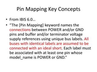
[Pin Mapping], page 23 From Radek: What is the relationship between pulldown_ref, and/or the gnd_clamp_ref bus declaration under the [Pin Mapping] keyword and the signal I/O reference node? Do we need to extend the [Pin Mapping] definition to cover signal I/O reference declaration? 4/1/2016 9
C_comp, page 33 Clarify last sentence? Similar clarifications needed elsewhere. 4/1/2016 10
Vinl and Vinh, pages 33,36 Specify references for Vinl and Vinh? [Model] and [Model Spec] Vinl/Vinh not even defined, other than comments in an example Clarification on page 10 (previous slide) might suffice. Need better definition for ECL/PECL 10/6/2024 11
Figures 1-2, pages 33-34 Change ground symbol to ? Show Vref as a voltage source symbol with two terminals? Show buffer reference terminals? Correct dangling 10/6/2024 12
[Voltage Range], [* Reference], pages 49-51 Change Description to clarify that these are voltage values? Nodes and voltage values are mixed up. Add figure showing terminals and supplies? Especially show what reference node of each supply is connected to. 10/6/2024 13
I-V table reference connections, page 53 [Pullup] source is referenced to a POWER pin? [Pulldown] source is referenced to a GND pin? For ECL [Pulldown] source is referenced to a GND or POWER pin? [POWER Clamp] source referenced to? [GND Clamp] source referenced to? With [Pin Mapping] it may not be pins? 10/6/2024 14
Figures 7-10, pages 57-59 Change Vcc to POWER? Show them as terminals? Show external sources in circuits? [Pullup Reference]? 10/6/2024 15
Figure 11, page 62 Change ground symbol to ? Show reference terminals connected through POWER and GND pins to external sources at [POWER Clamp Ref] and [GND Clamp Ref]. Show other types? 10/6/2024 16
Figure 15, page 72 Dangling? Only to show relationship of DUT & Fixture? 10/6/2024 17
Figure 16, page 72 Change ground symbol to ? Show all reference terminals connected through POWER and GND pins to external sources? Clarify absolute GND Clarify C_comp? Clarify last sentence? Separate diagram for ECL? [Voltage Range]? 10/6/2024 18
Figure 17, Page 73 Show all reference terminals connected through POWER and GND pins to external sources? Show Sig terminal connected to test fixture load? Is this DUT or DIA? L_VDDQ & R_VDDQ are on-die 10/6/2024 19
Table 12, pages 93-94 Clarify A_extref and A_gnd 10/6/2024 20
Figure 29, page 132 Is note 1 sufficient? Confusing use of GND as a signal name here. [Pin Mapping] can be used with [External Model] but not [External Circuit]? 10/6/2024 21