Overview of IBIS Interconnect Task Group Models
The IBIS Interconnect Task Group focuses on modeling package and on-die interconnects, with support for separate or combined interconnect models. They meet weekly to discuss contributions from major companies like Altera, Cadence, Intel, and more. The models include terminals for differential signals, supply, and graphics representation. The approach is consistent for IBIS and EBD files, with a focus on representing various interconnect components.

Download Presentation

Please find below an Image/Link to download the presentation.
The content on the website is provided AS IS for your information and personal use only. It may not be sold, licensed, or shared on other websites without obtaining consent from the author.If you encounter any issues during the download, it is possible that the publisher has removed the file from their server.
You are allowed to download the files provided on this website for personal or commercial use, subject to the condition that they are used lawfully. All files are the property of their respective owners.
The content on the website is provided AS IS for your information and personal use only. It may not be sold, licensed, or shared on other websites without obtaining consent from the author.
E N D
Presentation Transcript
IBIS Interconnect BIRD Draft 3 Walter Katz Signal Integrity Software, Inc. IBIS Summit, DesignCon Santa Clara, CA January 30, 2015
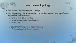
Overview IBIS Interconnect Task Group Models Represent Package and On-Die Interconnect On Die, Package, Supply and Signal Interconnect can be Combines or Kept Separate Similar Approach for Both IBIS and EBD Pre and Post Layout IBIS Files IBIS Interconnect Model Terminals Differential Signal (I/O) Model Terminals Supply Model Terminals Graphics Showing Model Terminals Corners Reconciling Legacy IBIS Models and [External Model][Interconnect Model] Next Steps 2
IBIS Interconnect Task Group Meets Wednesdays 8AM PDT http://www.eda.org/ibis/interconnect_wip/ Major Contributors Altera Cadence Design Systems Intel Corp Keysight Technologies Mentor Graphics Micron Technology Signal Integrity Software Synopsys Teraspeed Labs David Banas Bradley Brim Michael Mirmak Radek Biernacki Arpad Muranyi Justin Butterfield, Randy Wolff Walter Katz Rita Horner Bob Ross 3
Models Represent Package and On-Die Interconnect Languages Supported IBIS-ISS Touchstone Model Terminals Pins Die Pads Buffer Signals Buffer Supplies 4
On Die, Package, Supply and Signal Interconnect can be Combines or Kept Separate Supports separate on-die and package interconnect models and combined on-die and package interconnect models Independent Supply and Signal Interconnect Models Coupled Supply and Signal Interconnect Models Singled Ended and Differential Interconnect Models 5
Similar Approach for Both IBIS and EBD IBIS (.ibs) Interconnect Model Terminals Pins ([Pins]) Die Pads Buffers EBD (.ebd) Interconnect Model Terminals Pins ([Pin List]) reference_designator.pin EBD will be a separate BIRD based on the IBIS interconnect model BIRD when completed 6
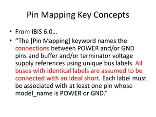
IBIS Interconnect Model Terminals Pins Die Pads Signal (I/O) Supply (POWER and GND) Buffers Signal (I/O) Supply Pullup Reference Pulldown Reference Power Clamp Reference Ground Clamp Reference External Reference 7
Pre and Post Layout IBIS Files Post Layout Signal (I/O) Terminals Pin, Die Pad and Buffer terminals referenced by Pin_name Supply Terminals Pin terminals referenced by Pin_name or Signal_name Die Pad terminals referenced by Die_Pad_name or Signal_name Buffer terminals referenced by Pin_name or Signal_name Pre Layout Signal (I/O) Terminals Referenced by Model_name Supply Terminals Referenced by Signal_name 8
Interconnect Model Terminals Terminal <terminal number> <At Pin|DiePad|Buffer> <ID> <What ID is> One line per terminal Supports both Pre and Post Layout Example Signal (I/O) Terminal records Post Layout Terminal 1 Pin_A_signal M8 Terminal 2 Pad_A_signal M8 Terminal 3 A_signal M8 Pre Layout Terminal 1 Pin_A_signal DQ Model_name Terminal 2 Pad_A_signal DQ Model_name Terminal 3 A_signal DQ Model_name 9
Differential Signal (I/O) Model Terminals Post Layout Terminal 1 Pin_A_signal M8 Terminal 2 Pin_A_signal M7 Terminal 3 Pad_A_signal M8 Terminal 4 Pad_A_signal M7 Terminal 5 A_signal M8 Terminal 6 A_signal M7 Pre Layout Terminal 1 Pin_A_signal_pos DQS Model_name Terminal 2 Pin_A_signal_neg DQS Model_name Terminal 3 Pad_A_signal_pos DQS Model_name Terminal 4 Pad_A_signal_neg DQS Model_name Terminal 5 A_signal_pos DQS Model_name Terminal 6 A_signal_neg DQS Model_name 10
Supply Model Terminals Post Layout Using Pins, Pads and Buffers Terminal 1 Pin_A_Signal B1 Terminal 2 Pin_A_Signal B2 Terminal 4 A_puref M3 Using Signal_name and Buffers Terminal 1 Pin_A_Signal VDD Signal_name Terminal 3 A_puref M3 Pre and Post Layout Using Signal_name and Pin mapping Terminal 1 Pin_A_Signal VDD Signal_name Terminal 3 A_Signal VDD Signal_name Using Signal_name and Model_name Terminal 1 Pin_A_Signal VDD Signal_name Terminal 3 A_puref DQ Model_name 11
Combined Package and On-Die Model Package Terminals Post Layout Pin_A_signal B3 A_puref A1 A_pcref A1 Pin_A_signal B4 Pullup Power Clamp Pin_A_signal A1 C_comp Model A_signal A1 Pulldown Ground Clamp Pin_Signal_name VSSQ A_gcref A1 A_pdref A1 Pin_Signal_name VSS
Combined Package and On-Die Model Package Terminals Post Layout Pin_A_signal B3 A_puref A1 A_pcref A1 Pin_A_signal B4 Pullup Power Clamp Pin_A_signal A1 C_comp Model A_signal A1 Pulldown Ground Clamp Pin_Signal_name VSSQ A_gcref A1 A_pdref A1 Pin_Signal_name VSS
Package Terminals Post Layout Package Model On-Die Model Pin_A_signal B3 Pad_A_signal VDD_pad A_puref A1 A_pcref A1 Pad_A_Signal VDDQ_pad Pin_A_signal B4 Pullup Power Clamp Pin_A_signal A1 C_comp Model Pad_A_signal A1 A_signal A1 Pulldown Ground Clamp Pad_Signal_name VSSQ Pin_Signal_name VSSQ A_gcref A1 A_pdref A1 Pad_Signal_name VSS Pin_Signal_name VSS
Corners Parameters can have either a single value or three corner values It is not clear if we will have a clear definition of the three corners Typ, Min, Max If a parameter is a length then Typ, Fast, Slow If a parameter is a delay then Typ, Slow, Fast If a parameter is an impedance then Typ, Min, Max Expect it will inherit the existing usage of Typ, Min and Max and will be up to EDA tool on how to apply these corners. Some Corner conditions (e.g. crosstalk) will be handled by [Interconnect Model Selector]. 15
Reconciling Legacy IBIS Models and [External Model] [External Model] supports an A_extref terminal which has no analog in legacy models (models that use the IV and VT curves). If new package models has a terminal to an [External Model] A_extref, how should the EDA tool terminate this terminal when using a legacy model? 16
Next Steps The goal is to complete the new interconnect model BIRD and formally submit it to the Open Forum by the end of Q1, 2015 Shortly thereafter with a BIRD to enhance EBD to support IBIS-ISS subckts. 17


 Model Terminals")