Understanding Pin Mapping and Interconnect in IBIS 6.0
Pin Mapping in IBIS 6.0 defines the connections between POWER/GND pins and buffer/terminator voltage supplies using unique bus labels. Interconnects between VDD pins and buffer supply terminals are crucial, with all pins associated with a named supply being shorted together. Draft 9 Interconnects and IBIS Pin Mapping concur on shorting pins connected to named supplies, ensuring a direct connection between buffer supply rails and pins. The necessity of specifying bus connections for each pin listed under the Pin keyword in Pin Mapping is highlighted, raising questions about flexibility in interconnect descriptions.

Download Presentation

Please find below an Image/Link to download the presentation.
The content on the website is provided AS IS for your information and personal use only. It may not be sold, licensed, or shared on other websites without obtaining consent from the author. Download presentation by click this link. If you encounter any issues during the download, it is possible that the publisher has removed the file from their server.
E N D
Presentation Transcript
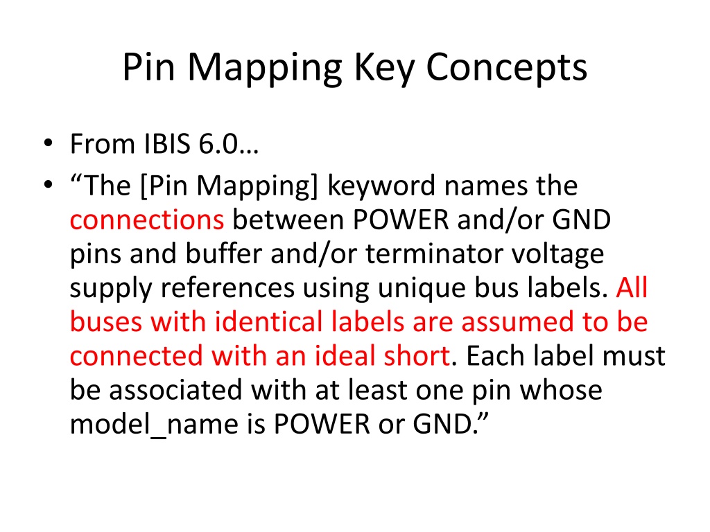
Pin Mapping Key Concepts From IBIS 6.0 The [Pin Mapping] keyword names the connections between POWER and/or GND pins and buffer and/or terminator voltage supply references using unique bus labels. All buses with identical labels are assumed to be connected with an ideal short. Each label must be associated with at least one pin whose model_name is POWER or GND.
Key Concepts (contd) The second column, pulldown_ref, designates the ground bus connections for the buffer or termination associated with that pin. The bus named under pulldown_ref is associated with the [Pulldown] I-V table for non-ECL [Model]s. The third column, pullup_ref, designates the power bus connection for the buffer or termination. The bus named under pullup_ref is associated with the [Pullup] table for non-ECL [Model]s
Pin Mapping in Interconnect BIRD In Draft 9... all pins with Signal_name VDD [connect to] to all Buffer supply terminals that are connected to Signal_name VDD as described in Pin_mapping. All Pins with Signal_name VDD are shorted together. All Buffer supply terminals that are connected to Signal_name VDD are shorted together
Example from Draft 9, P. 13 VDD: Interconnect between VDD Pins and individual buffer Pullup Reference. Terminal 1 Pin P1 Terminal 2 Pin P2 Terminal 3 Pin P3 Terminal 4 Pin P4 Terminal 5 Pin P5 Terminal 6 Buf_PURef A1 Terminal 7 Buf_PURef A2 Terminal 8 Buf_PURef A3 Terminal 9 Buf_PURef D1
Proposal Draft 9 and IBIS [Pin Mapping] agree on shorting of pins associated with a named supply [Pin] model_name must be POWER or GND [Pin Mapping] implies but does not state a direct connection (short) between the buffer supply rail and the pin Suggestion: For traditional interconnects, assume buffer rail/pin short For Draft 9 Interconnects([Interconnect Model] present), state that interconnect sits between buffer rail and pin Pin Mapping rails still shorted to each other Pin Mapping pins on named supplies still shorted together
Additional Issue From IBIS 6.0 If the [Pin Mapping] keyword is present, then the bus connections for EVERY pin listed under the [Pin] keyword must be given. Does this prevent effective use of Draft 9 Interconnects? Partial interconnect descriptions become impossible

")