Nanofabrication Design Review Meeting for Microfluidic Mixer Development
Evaluating the design, fabrication, and testing of a passive three-dimensional micromixer incorporating split and recombine structures for efficient mixing at varying flow rates. Comsol multi-physics simulations optimized channel parameters resulting in a compact mixer design with enhanced mixing capabilities.

Download Presentation

Please find below an Image/Link to download the presentation.
The content on the website is provided AS IS for your information and personal use only. It may not be sold, licensed, or shared on other websites without obtaining consent from the author. Download presentation by click this link. If you encounter any issues during the download, it is possible that the publisher has removed the file from their server.
E N D
Presentation Transcript
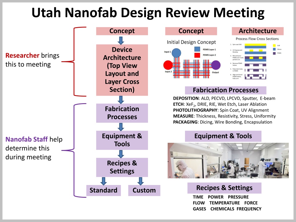
Utah Nanofab Design Review Meeting Concept Concept Architecture Device Architecture (Top View Layout and Layer Cross Section) Researcher brings this to meeting Fabrication Processes DEPOSITION: ALD, PECVD, LPCVD, Sputter, E-beam ETCH: XeF2, DRIE, RIE, Wet Etch, Laser Ablation PHOTOLITHOGRAPHY: Spin Coat, UV Alignment MEASURE: Thickness, Resistivity, Stress, Uniformity PACKAGING: Dicing, Wire Bonding, Encapsulation Fabrication Processes Equipment & Tools Equipment & Tools Nanofab Staff help determine this during meeting Recipes & Settings Recipes & Settings Standard Custom TIME POWER PRESSURE FLOW TEMPERATURE FORCE GASES CHEMICALS FREQUENCY
Title of Research Project or Device To Be Fabricated Researcher Name PI Name Date
Design Concept Goals: Approach
Device Architecture Top View and Cross Section Process Flow
Proposed Materials and Fabrication Processes Materials Substrate Thin films/coatings Chemicals Processes Deposition Thin Films Coatings Patterning Photoresists Etching Packaging Dicing Wirebonding Test and Measurement Electrical Mechanical Optical Fluidic
Example: Microfluidic Mixer Brian Baker Dr. Bruce Gale July 4, 2016
Example: Abstract challenging due to the laminar nature of fluids at the microscale. This study evaluates the design, fabrication, and testing of a passive three-dimensional micromixer that incorporates split and recombine structures that promote mixing at low flows with chaotic advection features that mix well at high flows. Comsol multi-physics simulations were performed to optimize the number of parallel channels, the channel width, and the number of split and recombine stages in the mixer. Overall mixer area was less than 4 mm2, and consisted of 19 stages of two parallel overlapping channels with a depth of 100 microns and a width of 50 microns. Soft lithography was used to fabricate the two-layer device, and during the assembly process a partial cure of PDMS was found to be especially useful for enabling successful alignment. Test results show mixing efficiencies above 92% across a range of flows from 0.1 mL/hr to 10 mL/hr, with a range of Reynold s numbers from 0.28 to 28. At an intermediate flow rate of 1 mL/hr, a pressure drop of 1.7 kPa was measured, and the mixing speed was 98 milliseconds. Results show that combining two types of mixer structures in this manner can create high mixing efficiency with reduced overall mixer size. Mixing fluids over a wide range of flows inside microfluidic systems is
Example: Design Concept PDMS Layer 1 Input 1 PDMS Layer 2 Input 2 Output Goals: Increase mixing effectiveness/decrease time to mix at three flow rates Minimize pressure drop Minimize total area and length of mixer Simplify fabrication Build and test mixer based on simulation results Approach Split and recombine multiple times results in many laminate layers Long, narrow channels increase diffusion Multiple parallel channels decrease pressure drop
Example: Device Architecture Top View and Cross Section Process Flow 1. Spin coat SU8 SU8 Silicon 2. UV Expose and Develop PDMS 3. Mix and pour PDMS over mold, partial cure 4. Remove PDMS halves 5. Poke inlet holes in PDMS 6. Align and bond PDMS halves, fully cure
Example: Proposed Materials and Fabrication Processes Materials Substrate 4 Silicon p-type wafer Thin films/coatings SU8 2050 Chemicals Sylgard 184 PDMS SU8 Developer Processes Deposition Coatings Sylgard 184 pour, vacuum degas and partial oven cure Patterning Photoresists SU8 spin and develop Align PDMS halves and fully cure Packaging Bore holes using coring tool Press fit fluidic tubes into inlet and outlet ports Test and Measurement Optical Microscope images of flows and mixing Fluidic Dual syringe pump with controlled flows and pressure gauge Colored water for enhanced mixing imaging
Example: References Squires, Todd M., and Stephen R. Quake. "Microfluidics: Fluid physics at the nanoliter scale." Reviews of modern physics 77.3 (2005): 977. Nguyen, Nam-Trung, and Zhigang Wu. "Micromixers a review." Journal of Micromechanics and Microengineering 15.2 (2005): R1. Capretto, Lorenzo, et al. "Micromixing within microfluidic devices." Microfluidics. Springer Berlin Heidelberg, 2011. 27-68. Chen, Hao, and Jens-Christian Meiners. "Topologic mixing on a microfluidic chip." Applied Physics Letters 84.12 (2004): 2193-2195. SU8 Datasheet: http://microchem.com/pdf/SU- 82000DataSheet2025thru2075Ver4.pdf, downloaded April 29, 2013.