Basics of Nanofabrication
CNWS aims to assist integration lab users community in addressing fabrication challenges, discussing advanced topics, offering group discussions, and presentations on various aspects of nanofabrication.

Download Presentation
Please find below an Image/Link to download the presentation.
The content on the website is provided AS IS for your information and personal use only. It may not be sold, licensed, or shared on other websites without obtaining consent from the author. Download presentation by click this link. If you encounter any issues during the download, it is possible that the publisher has removed the file from their server.
Presentation Transcript
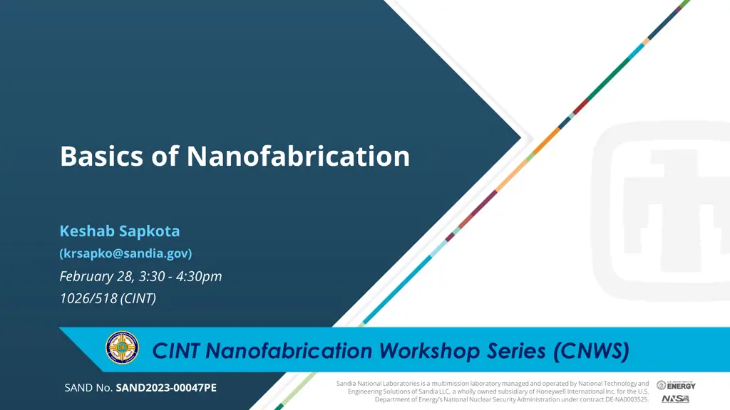
Basics of Nanofabrication Keshab Sapkota (krsapko@sandia.gov) February 28, 3:30 - 4:30pm 1026/518 (CINT) CINT Nanofabrication Workshop Series (CNWS) Sandia National Laboratories is a multimission laboratory managed and operated by National Technology and Engineering Solutions of Sandia LLC, a wholly owned subsidiary of Honeywell International Inc. for the U.S. Department of Energy s National Nuclear Security Administration under contract DE-NA0003525. SAND No. SAND2023-00047PE 1
CINT Nanofabrication Workshop Series (CNWS) Goals: Help integration lab (IL) users community to Goals: Help integration lab (IL) users community to Smooth out learning curve for new users with no/little prior fabrication experience Address fabrication bottlenecks for the users and minimize/avoid rediscovering the wheel Discuss advanced fabrication topics with experts and learn from each other Workshop Topics Workshop Topics Introductory Topics Introductory Topics Planning & design, fab process flow, sample handling, troubleshooting Workshop Format Workshop Format Group Discussion (15 minutes) (15 minutes) Intermediate Topics Intermediate Topics Lithography, chemical processes, etching, depositions, metrology, holistic approach, troubleshooting New IL Users Presentation on the Topic (30 minutes) (30 minutes) (30 min) (30 min) Discussion on user s fab issues (15 minutes) (15 minutes) Advanced Topics Advanced Topics Materials specific, device architecture specific, complex process flow, integration Existing IL Users
What is Nanofabrication? Nanofabrication is a process of creating nanoscale structures Nanofabrication is primarily a top-down process www.firstnano.com/portfolio-item/silicon-nanowires-sem-10-k-x Dhindsa, Nanotechnology, 25(2014) Bottom Bottom- -up synthesis: VLS growth up synthesis: VLS growth Top Top- -down fabrication: Etching down fabrication: Etching Different approaches of creating nanostructures Different approaches of creating nanostructures
What is Nanofabrication? Nanofabrication is a process of creating nanoscale structures Nanofabrication is primarily a top-down process Nanofabrication inherits the traits of microfabrication Nanofabrication is primarily a planar process, can be obtain 3D shapes in some special cases Lithography Lithography Development Development Microscale process at CINT Microscale process at CINT Nanoscale process at CINT Nanoscale process at CINT Nanofabrication has similarity with microfabrication but Nanofabrication has similarity with microfabrication but involves additional complexities due to reduced size involves additional complexities due to reduced size GaN GaN 3D structures 3D structures (Sandia) (Sandia) Example of a planar process Example of a planar process
Components of Nanofabrication Films processing Films processing Oxides, nitrides, poly-Si, (ALD, CVD) Additional treatments Additional treatments RTA, annealing, passivation, protection Process Sample preparation Sample preparation sample/substrate Sample cleaning, mounting, transfer Create patterns on polymer (photoresist) Transfer pattern to sample/substrate Lithography Lithography Etch/Liftoff Etch/Liftoff Metal dep, dry etch, wet etch e-beam, photo, imprint
CINT cleanroom capabilities LP-CVD, PE-CVD, ALD Poly-si, dielectrics (SiO2, SiNx, Al2O3, TiO2, & more) Wet benches, dicing tool, lapper, scribers, Plasma/UV/Ozone cleaning Sample preparation CVD, ALD Diced sample Diced sample Asher Asher LP LP- -CVD CVD Dry etch: Plasma milling, RIE, ICP, BOSCH Chemistry: Cl2, BCl3, O2, Fl, Ar, CH4, SF6 Well developed processes for Si, SiGe, GaN, GaAs, Diamond, & more Mask aligners, Laser writer (MLA), 100 kV EBL, 30kV EBL, FIB Photolitho resolution ~ 1 um EBL resolution down to 10 nm Lithography, Patterning Etching MLA MLA ICP ICP EBL EBL Optical microscopes, SEMs, reflectometers, profilometer E-beam evaporators, thermal evaporators, RF/DC sputterer Materials: metals, alloys, dielectrics, semiconductors PVD dep Metal/Dielectric Metrology SEM SEM NanoSpec NanoSpec
Design of Fabrication Device needs Theory and simulation Test a concept/theory, prototyping Fabrication shape, size, resolution Materials stack, compatibility, integration needs Measurement requirements Identify sample size, design pattern Step by step process flow based on parameters Identify steps that need testing/optimization Work in parts: Work in parts: test/optimize unknown steps- can be parallelized, may need multiple experiments Put them together Put them together once individual steps are tested Define problem, set goals Identify parameters Identify Fab process Feedback Execute Fab Inspect/measure sample at each step when possible Use reference sample with primary sample to enable additional measurements Measurement & Analysis
Identifying fabrication process flow Fail to plan is a plan to fail Design of Fabrication (Parameters) Inefficient but excellent process or efficient but ok process? Inefficient but excellent process or efficient but ok process? Write down step by step fabrication process flow Unoptimized process step? Iterative optimization # of test runs Y Available tools Feasibility Example: How to design an optimal process? Example: How to design an optimal process? Goal: fabricate 100nm wide 4 metal fingers with 150x150 um Goal: fabricate 100nm wide 4 metal fingers with 150x150 um2 2 contact pads which of the following is a desired approach? pads which of the following is a desired approach? 1. Use EBL to write 100nm fingers (write time 1 min) & MLA to write contact pads (1 minutes) 2. Use EBL to write entire pattern (write time 1 hours) contact Determine if the planned fabrication is feasible. Determine if the planned fabrication is feasible. Tool limited: Tool limited: covering 2 inch wafer by dense array of EBL patterned 100nm features not possible Policy restricted: Policy restricted: 1um thick gold layer not allowed to deposit >300nm Process limited: Process limited: 50um deep plasma etched trench on sapphire very difficult
Executing design of fabrication Diamond etching Diamond etching Detail fab plan example HSQ mask HSQ mask HSQ mask HSQ mask RIE/ICP = 250W/550W, O plasma Result: smooth profile but excessive lateral etch RIE/ICP = 100W/550W, O plasma Result: etching but rough floor RIE/ICP = 250W/550W, O-plasma Result: good etch profile Etch rate = 6nm/s Etch depth = 1um Ti:Diamond selectivity = 1:40 Ti Ti mask mask
Optimization Controllable: Resist thickness, dose, plasma power Controllable: Resist thickness, dose, plasma power Partially controllable: Photoresist edge beads Partially controllable: Photoresist edge beads Uncontrollable: Tools dependent variation Uncontrollable: Tools dependent variation Uncontrolled: humidity and its impact on photoresist film Uncontrolled: humidity and its impact on photoresist film Design of Fabrication Design of Fabrication Define problem, set goals Controlled Controlled variables variables Uncontrolled Uncontrolled variables variables Identify parameters Identify Fab process Error Error Feedback Yield Yield Optimize process Execute Fab Iteration Iteration Measurement & Analysis Unknown Unknown variables variables Optimization of a process by iteration Optimization of a process by iteration
Documentation Best practice: keep track of every small detail in the fab process Fabrication experiment generates multi-dimensional data Iterative Iterative optimization optimization Different batches Different batches Optimize Optimize step step 1 1 Batch Batch 1 1 Although you show Although you show one best image, your one best image, your generate a lot of data generate a lot of data in the process in the process -----Data --- -Process track -Images -Metrology data Batch Batch 2 2 Optimize Optimize step step n n Available tools to manage data Available tools to manage data Track everything in one place Track process, data, docs,, PowerPoint Track process, data, images Cleanroom notebook to track process 11
Common Fabrication Steps: Sample Preparation Sample size: use dicing tool scriber to cut sample/ substrate to desired size Sample cleaning Sample cleaning Samples with gunk Leftover hydrocarbon after liftoff Metal particles Acetone airbrush, Acetone airbrush, Methanol, IPA Methanol, IPA Oxygen plasma (Barrel Oxygen plasma (Barrel ash, ozone, LOLA) ash, ozone, LOLA) Ammonia peroxide, Ammonia peroxide, piranha piranha Hydrocarbon/gunk removal: Acetone airbrush Acetone airbrush (forceful), IPA (forceful), IPA Ammonia peroxide Ammonia peroxide (some), piranha (~all) (some), piranha (~all) Metal particles removal: HF, BOE (removes HF, BOE (removes different oxides) different oxides) Hot bases e.g. KOH (removes Hot bases e.g. KOH (removes Al Al2 2O O3 3, SiO Oxide removal: , SiO2 2, attacks Si , attacks Si 12
Common Fabrication Steps: Lithography 30kV EBL (SEM) 30kV EBL (SEM) Resolution down to 30nm No straight forward proximity correction Smaller area EBL, no stitching 100 kV EBL 100 kV EBL Resolution down to 10nm, high beam current (20nA) Large area wafer scale patterning, stitching Proximity correction included for extreme res patterning Preferred samples size > 9mm Choosing right tools Choosing right tools Dense patterns 1mm long 250nm wide lines Small samples Patterning Patterning contacts on 2D/1D contacts on 2D/1D nanostructures nanostructures MLA MLA Mask aligner Mask aligner Prototyping Prototyping photolitho photolitho Maskless write from CAD Resolution ~1um Good speed Image reversal Image reversal photolithography photolithography process process Uses mask to align and pattern optically Mask based Mask based photolitho photolitho
Common Fabrication Steps: Lithography- Choosing right tool 1mm long 250nm wide lines Patterning Patterning contacts on 2D/1D contacts on 2D/1D nanostructures nanostructures Dense patterns Small samples 30kV EBL (SEM) 30kV EBL (SEM) Resolution down to 30nm No straight forward proximity correction Smaller area EBL, no stitching 100 kV EBL 100 kV EBL Resolution down to 10nm, high beam current (20nA) Large area wafer scale patterning, stitching Proximity correction included for extreme res patterning Preferred samples size > 9mm Image reversal Image reversal photolithography photolithography process process Prototyping Prototyping photolitho photolitho Mask based Mask based photolitho photolitho MLA MLA Mask aligner Mask aligner Maskless write from CAD Resolution ~1um Good speed Uses mask to align and pattern optically
Common Fabrication Steps: Lithography Typical Process Typical Process Create design. Free (and best) software: Klayout Bake sample to remove moisture, coat primer to enhance adhesion if necessary Spin coat photoresist single/multilayer single/multilayer, thickness > 2xmetal dep thickness for good liftoff Correct proximity & test dose test for given patterns Klayout Intuitive to design pattern Python library to generate pattern for given patterns Some e-beam resists Dose test: Increased dose
Common Fabrication Steps: Pattern transfer Pattern transfer, a planner process, depends on the 3D parameters e.g., resist thickness, mask thickness, undercuts, lateral dimensions, etc. Pattern transfer by liftoff Pattern transfer by liftoff Clean developed pattern (e.g. Dscum, BOE, etc) for good adhesion and contact Non-conformal metal dep, soak in acetone/PG remover Things to consider Things to consider Typical adhesive metal layers: Ti, Ta, Cr Dep rate, grains formation & film quality, heat transfer Resist cracking & burn out due to excessive heating Lithography Lithography Development Development Pattern transfer Pattern transfer by Liftoff by Liftoff Pattern transfer Pattern transfer by etching by etching
Common Fabrication Steps: Pattern transfer Pattern transfer, a planner process, depends on the 3D parameters e.g., resist thickness, mask thickness, undercuts, lateral dimensions, etc. Pattern transfer by etching Pattern transfer by etching Polymer as a mask, metal mask, dielectric mask Dry: Milling (physical) or reactive etching (chemical) -Anisotropic Wet: Isotropic or crystal plane selective Plasma etch (aniso) Things to consider Things to consider Mask to material etch selectivity RIE (highly anisotropic), ICP (high power plasma), or milling Temperature and high energy plasma heating Examples: Cl-plasma for GaN, III-V semiconductor, F-plasma for Si/Ge, BOSCH cycle for deep etching Ion milling for metals Wet etch: acid or base (oxides can be etched by both HF and hot bases), temperature, selectivity, safety Wet etch (iso) GaN in KOH Wet etch (Crystal plane selective)
Troubleshooting Error propagation and Error propagation and uncertainty in outcome uncertainty in outcome Sample prep Pattern transfer Post process Patterning Common troubleshooting steps Common troubleshooting steps Track the note and identify if this is human error Check if steps are exactly followed. Was there any step skipped? Was there a change in tool such as recent maintenance, software updates? Was the chemical used expired? If issue not solved If issue not solved Use reference samples created in each steps to inspect back to the process Narrow down the process step(s) that might have caused the issue and re-test that step(s) Literatures: incompatible chemistry, process Subject Matter Experts (SME) help 18

")