Novel Control Methods of DC-DC Converters in Electrical Engineering

Introduction to a novel control method of DC-DC converters in electrical engineering focusing on various converter topologies, closed-loop control techniques, performance comparison of controllers, and drawbacks with modifications. The presentation covers essential aspects such as regulation, converter operation under variable conditions, and basic converter topologies like buck, boost, buck-boost, Cuk, and full bridge converters. It also discusses switch-mode DC-DC converters and solutions to drawbacks encountered in practical circuits.

Download Presentation

Please find below an Image/Link to download the presentation.
The content on the website is provided AS IS for your information and personal use only. It may not be sold, licensed, or shared on other websites without obtaining consent from the author. Download presentation by click this link. If you encounter any issues during the download, it is possible that the publisher has removed the file from their server.
E N D
Presentation Transcript
1 Dept. of EEE, GEC, Thrissur A NOVEL CONTROL METHOD OF DC-DC CONVERTERS Dr.M.Nandakumar Professor Department of Electrical engineering Govt. Engineering College Thrissur
2 Dept. of EEE, GEC, Thrissur Outline Introduction DC-DC converter topologies Buck converter Closed loop control of buck converter using PI controller One cycle control Buck converter using OCC Boost converter Boost converter using PI controller Boost converter using OCC One Cycle Control of Buck Boost converter Performance comparison of PI and OCC controller conclusion
3 Dept. of EEE, GEC, Thrissur Introduction DC-DC converters are subjected to variable input/ variable output conditions Regulation of converter operation is an essential requirement Closed loop controller is used for the regulation of out put voltage 1. Line Regulation 2. Load regulation
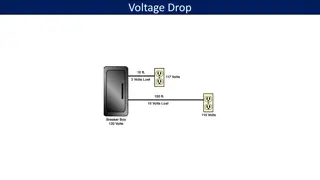
4 Dept. of EEE, GEC, Thrissur DC-DC conversion techniques an introduction Case 1 : Voltage divider Case 2 : Linear series regulator 10A 10A 10A Vdc=100V + - dc-dc converter 50V 5 Vo=50V 5 Vo=50V Vo=50V LA& BD 5 Ploss=500W Vdc=100V Vdc=100V Vref LA&BD- Linear Amplifier & base driver Ploss=500W 1 S L Vdc 2 Vo C
DC- DC CONVERTER TOPOLOGIES Buck converter or step - down converter Boost converter or step - up converter Buck-Boost converter or step-down/up converter Cuk converter Full Bridge converter Only step-down and step-up are the basic converter topologies Both buck-boost and cuk converters are combination of these basic topologies Full bridge converter is derived from step-down converter
6 Dept. of EEE, Govt. Engg. College, Thrissur Switch-mode dc-dc converter
7 Dept. of EEE, Govt. Engg. College, Thrissur Drawbacks and modifications of the circuit Drawbacks In practical circuits, load will be inductive (even for resistive load due to stray inductance) leading to dissipate or absorb the inductive energy which may destroy the switch Output voltage fluctuates between 0 and Vd Modifications Problem of stored inductive energy is overcome using freewheeling diode Output voltage fluctuation are very much diminished using Low pass Filter
8 Dept. of EEE, GEC, Thrissur Buck converter (Step-down converter)
9 Dept. of EEE, GEC, Thrissur Sep-down dc-dc converter 1 = Cut off frequency of low pass filter, cf 2 LC
10 Dept. of EEE, GEC, Thrissur Step-down converter circuit states (Continuous Conduction Mode)
11 Dept. of EEE, GEC, Thrissur Volt-sec balance (cont.) Under steady state operation the integral of the inductor voltage vL over one time period must be zero T t T s on s 0 0 on T = + = 0 v dt v dt v dt L L L t + = ( ) ( )( ) 0 V V t V t 0 d o on s on V V t = = o on T D d s
12 Dept. of EEE, GEC, Thrissur Buck converter (Step-down converter) in CCM In Continuous Conduction Mode (CCM), neglecting power losses associated with all circuit elements, the input power Pd is equal to output power Po = V I V I d d o o 1 D I I V V = = o d 0 d V V t = = o on T D d s Io is the average output current and Id is the average input current Hence in CCM step down converter is equivalent to a dc transformer (step down)
13 Dept. of EEE, GEC, Thrissur Closed loop control of buck converter
14 Dept. of EEE, GEC, Thrissur Closed loop control of Buck Converter (with fixed input)
15 Dept. of EEE, GEC, Thrissur Closed loop control of Buck Converter (with fixed input)-output voltage
16 Dept. of EEE, GEC, Thrissur Buck converter using PI controller
17 Dept. of EEE, GEC, Thrissur Transient performance of PI controller
18 Dept. of EEE, GEC, Thrissur Closed loop control of Buck Converter with input voltage perturbations - line regulation
19 Dept. of EEE, GEC, Thrissur Closed loop control of Buck converter Input (changes form 14 V to 20V) and output voltage wave forms using PI controller
20 Dept. of EEE, GEC, Thrissur In PWM control, the duty ratio is modulated in a direction that reduces the error. When the input voltage is perturbed, that must be sensed as an output voltage change and error produced in the output voltage is used to change the duty ratio to keep the output voltage to the reference value. This means it has slow dynamic response in regulating the output in response to the change in input voltage.
21 Dept. of EEE, GEC, Thrissur One cycle control (OCC) One cycle control Non linear control technique. Uses the concept of control of average value of switching variable.
22 Dept. of EEE, GEC, Thrissur Buck converter using One Cycle control (OCC) K. M. Smedley, Control Art of Switching Converters, Ph.D. Thesis, California Institute of Technology, 1990. Controls the duty ratio of switch such that the average value of switched variable is equal to or proportional to the control reference in each cycle The output voltage of the buck converter is the average value of the switched variable vs. 1 = ( ) t ( ) v v t dt int in RC 1 f V = in t RC 1 f
23 Dept. of EEE, GEC, Thrissur Buck converter using One Cycle control (cont.)
24 Dept. of EEE, GEC, Thrissur Power Source Perturbation Rejection 1 = ( ) ( ) v t v t dt 0 in RC 1 f V = in t RC 1 f Here, the input perturbation will immediately cause a change in slope of the integration within one switching period. As a result duty ratio changes and output voltage do not change even if power a source having a disturbance. Ie if input suddenly increases the slope of integrator output (= ) increases and it reaches the reference voltage Vref early and ON period reduces and OFF period increases leading to reduction of duty ratio D V in RC 1 f
25 Dept. of EEE, GEC, Thrissur Change in Reference Voltage When the control reference is perturbed by a large step up, the time taken to reach the new control reference increase (slope of integration remains the same since Vin is not changing)); therefore the duty ratio is larger. When the control reference is lower, the duty ratio is smaller.
26 Dept. of EEE, GEC, Thrissur Buck converter with one cycle control Clock frequency =10 kHz Or Clock period = 0.1msec K= 1/Ts = 10000
27 Dept. of EEE, GEC, Thrissur Buck converter with one cycle control (cont.) Input voltage and output voltage
28 Dept. of EEE, GEC, Thrissur Performance comparison between OCC and PI during input voltage perturbation a b c (a)Input voltage perturbation (b) Output voltage using OCC (c) Output voltage using PI controller
29 Dept. of EEE, GEC, Thrissur Buck converter using OCC with reference voltage perturbation
30 Performance comparison between OCC and PI during output voltage reference perturbation Dept. of EEE, GEC, Thrissur a b c (a)output reference perturbation (b) Output voltage using OCC (c) Output voltage using PI controller
31 Dept. of EEE, GEC, Thrissur Step-up (Boost) Converter
32 Dept. of EEE, GEC, Thrissur Volt-sec balance Boost converter
33 Dept. of EEE, GEC, Thrissur Volt-sec balance Boost converter (cont.) Boost converter circuit while the switch is position 1 Boost converter circuit while the switch is position 2
34 Dept. of EEE, GEC, Thrissur Boost Converter in Continuous Conduction Mode
35 Dept. of EEE, GEC, Thrissur Boost Converter in Continuous Conduction Mode Inductor voltage in boost converter
36 Dept. of EEE, GEC, Thrissur Boost Converter in Continuous Conduction Mode (cont.) In steady state the time integral of the inductor voltage over one time period must be zero ( ) ( )(1 1 1 d V D Assuming a lossless circuit, Pd = Po + = 0 D T d on V t V DT V V V t d V o V off + = ) 0 0 d s d s = 0 = V I I I V I 0 0 d d = 0 (1 ) D d Io is the average output current and Id is the average input current Hence in CCM step up converter is equivalent to a dc transformer (step up)
37 Dept. of EEE, GEC, Thrissur Closed Loop Control of Boost Converter
38 Dept. of EEE, GEC, Thrissur
39 Dept. of EEE, GEC, Thrissur BOOST converter + = ( + ) 0 D T d on V t V DT V V V V t d V o V off = ( )(1 ) 0 0 d s d s 1 = 0 1 D d In closed loop, output voltage Vo should be equal to reference voltage Vref, Hence equation can be rewritten as ??= ???? = ?? 1 ? ??? ???? ?? =1 ???? ?? = ????.? ????.?? ?? 0
40 Dept. of EEE, GEC, Thrissur Simulation of Boost converter using OCC V = = d V V o ref 1 D ON T 1 T = = V V DV V dt ref d ref ref s 0
41 Performance comparison between OCC and PI during input voltage perturbation Dept. of EEE, GEC, Thrissur a b c (a)Input voltage perturbation (b) Output voltage using OCC (c) Output voltage using PI controller
42 Performance comparison between OCC and PI during output voltage reference perturbation Dept. of EEE, GEC, Thrissur a b c (a)output reference perturbation (b) Output voltage using OCC (c) Output voltage using PI controller
43 Dept. of EEE, GEC, Thrissur BUCK-BOOST Converter + = ( )(1 ) 0 V DT V V V D T d s o s D = o 1 D d ??? ????(1 ?) = ???.? ????=1 (??? + ????).?? ?? 0
44 Dept. of EEE, GEC, Thrissur BUCK-BOOST Converter -OCC In closed loop, the output voltage Vo should be equal to reference voltage Vref Hence by rewriting the equation, = (1 = ) V D DV + ref d ( ) V D V V ref d ref ON T 1 T = + ( ) V V V dt ref d ref s 0
45 Dept. of EEE, GEC, Thrissur Closed loop control of Buck boost converter using OCC D = = V V V 0 d ref 1 D D = (1 = ) V DV + ref d ( ) V D V V ref d ref ON T 1 T = + ( ) V V V dt ref d ref s 0
46 Performance comparison between OCC and PI during input voltage perturbation Dept. of EEE, GEC, Thrissur a b c (a)Input voltage perturbation (b) Output voltage using OCC (c) Output voltage using PI controller
47 Performance comparison between OCC and PI during output voltage reference perturbation Dept. of EEE, GEC, Thrissur a b c (a)output reference perturbation (b) Output voltage using OCC (c) Output voltage using PI controller
48 Dept. of EEE, GEC, Thrissur OCC vs. PI OCC PI Buck converter input voltage variation Settling time 6ms 35ms Maximum steady state deviation from 0.8V 4.2V Buck converter reference voltage variation Settling time 4ms 40ms Maximum steady state deviation from 0.5V 0.2V Boost converter input voltage variation Settling time 1ms 50ms Maximum steady state deviation from 0.1V 9V Boost converter reference voltage variation Settling time 10ms 25ms Maximum steady state deviation from 1V 1V Buck Boost converter input voltage variation Settling time 6ms 25ms Maximum steady state deviation from 1V 5V Buck Boost converter reference voltage variation Settling time 4ms 25ms Maximum steady state deviation from 2V 2V
49 Dept. of EEE, GEC, Thrissur PI Vs. OCC :-Settling time performance 60 50 40 OCC 30 PI 20 10 0 1 2 3 4 5 6 1:- buck input perturbation 2:- buck output reference perturbation 3:- boost input perturbation 4:- boost output reference perturbation 5:- buck boost input perturbation 6:- buck boost output reference perturbation
50 Dept. of EEE, GEC, Thrissur Conclusion Compared to PI controller, OCC gives a better transient performance for DC-DC converter. Less settling time Less maximum deviation from steady state Can find wide applications in drives and renewable energy sources.