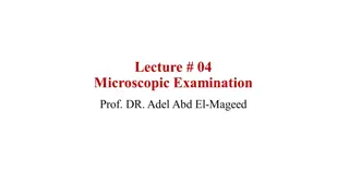
Transmission Electron Microscopy (TEM)
Transmission electron microscopy (TEM) is a
microscopy
technique in which a beam of
electrons
is transmitted through an ultra-
thin specimen, interacting with the specimen as it passes through it. An image is formed from the interaction of the electrons
transmitted through the specimen; the image is magnified and
focused
onto an imaging device. Higher resolution imaging requires
thinner samples and higher energies of incident electrons, which means that the sample can no longer be considered to be
absorbing electrons. Resolution in TEM ranges from few nanometers to atomic level ( Angstrom).
TEMs consist of the following components:
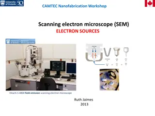
An electron source
Thermionic Gun
Electron beam
Electromagnetic lenses
Vacuum chamber
2 Condensers
Sample stage
fluorescent screen
Computer
Fig -1- instrument of TEM
TEM provides information on :
1.
Topography
2.
Morphology
3.
Compositional
4- Crystalline
Sample preparation
Sample preparation in TEM can be a complex procedure. TEM specimens are required to be at most hundreds of nanometers
thick. High quality samples will have a thickness that is comparable to the mean free path of the electrons that travel through
the samples.
Materials that have dimensions small enough to be electron transparent, such as powders or nanotubes, can be quickly prepared
by the deposition of a dilute sample containing the specimen onto support grids or films. In the biological sciences in order to
withstand the instrument vacuum and facilitate handling, biological specimens can be fixated using either a
negative
staining material such as uranyl acetate .
In material science and metallurgy must be prepared as a thin foil, or etched so some
portion of the specimen is thin enough for the beam to penetrate.
Fig -2- preparation of powder sample for TEM
Imaging in TEM
During transmission, the speed of electrons directly correlates to electron wavelength; the faster electrons move, the shorter
wavelength and the greater the quality and detail of the image. Imaging method in TEM are :
1- Diffraction Contrast
There are two basic modes of TEM operation, namely the bright-field mode, where the transmitted beam contributes to the
image, and the dark-field imaging mode, in which the diffracted beam contributes to the image. Dark field mode is good to
observe nanoparticles because the light up due to the high scattering.
Fig -3- bacillus with gold nanoparticles (a) bight field mode ,
(b) dark field mode
Phase Contrast
PHASE CONTRAST in TEM images can arise due to the differences in the phases of the electron waves scattered through a
thin specimen. The method is capable of resolving sub-unit-cell detail. Whereas conventional bright- and dark-field TEM
resolution 1-3 nm. Phase contrast imaging is the basis for the co called high-resolution TEM (HRTEM). For a structurally
ordered crystal, the method produces an image that shows the periodicity of the crystal lattice and hence is sometimes
called lattice imaging
Fig -4- HRTEM of graphene layer
Fig -5- HRTEM of Si and SiO2 phases
Diffraction in TEM
Samples can exhibit diffraction contrast, whereby the electron beam undergoes
Bragg scattering
,
which in the case of a
crystalline sample. Selected area electron diffraction (SAED) can be used to determine whether a specimen is single crystal,
polycrystalline, or amorphous; identify the crystallographic structure, symmetry, and orientation of samples; measure the lattice
parameter; identify if more than one phase is present. Single spots appear only when the beam is diffracted by a single crystal.
Polycrystalline materials gives ring patterns analogous
Fig -6- SAED for single crystal (left image), polycrystalline ( right image)
Fig -7- SAED pattern of polycrystalline materials
Electron energy-loss spectroscopy (EELS)
Electron energy-loss spectroscopy (EELS) is an analytical technique that measures the change in kinetic energy of electrons
after they have interacted with a specimen.
Electron energy-loss spectroscopy (EELS) involves measurement of the amount of
energy needs to remove the electron from the shells
Zero-loss peak at 0 eV:
It mainly contains electrons that still have the original beam energy E
0
, i.e., they have only interacted elastically or not at all with
the specimen ( incident electrons do not loss any energy).
Low-loss region (< 100eV)
Here, the electrons that have induced
plasmon
oscillations occur.
High-Loss region (> 100eV)
For the ionization of atoms, a specific minimum energy, the critical ionization energy E
C
or ionization threshold, must be transferred
from the incident electron to the expelled inner-shell electron, which leads to ionization edges in the spectrum at energy losses
that are characteristic for an element. Thus, EELS is complementary to
X-ray spectroscopy
, and it can be utilized for qualitative and
quantitative element analysis as well.
Fig -8- EELS of Vanadium oxide nanotube
Transmission Electron Microscopy (TEM) is a powerful microscopy technique that uses a beam of electrons to create high-resolution images of ultra-thin specimens. It provides detailed information on topography, morphology, composition, and crystalline structure. Sample preparation for TEM is crucial, requiring specimens to be extremely thin. Imaging in TEM is based on diffraction contrast and phase contrast, allowing for detailed analysis at the atomic level. Various modes of operation, such as bright-field and dark-field imaging, offer unique insights into different types of specimens.

Download Presentation

Please find below an Image/Link to download the presentation.
The content on the website is provided AS IS for your information and personal use only. It may not be sold, licensed, or shared on other websites without obtaining consent from the author.If you encounter any issues during the download, it is possible that the publisher has removed the file from their server.
You are allowed to download the files provided on this website for personal or commercial use, subject to the condition that they are used lawfully. All files are the property of their respective owners.
The content on the website is provided AS IS for your information and personal use only. It may not be sold, licensed, or shared on other websites without obtaining consent from the author.
E N D
Presentation Transcript
Transmission electron microscopy (TEM) is a microscopy technique in which a beam of electrons is transmitted through an ultra- thin specimen, interacting with the specimen as it passes through it. An image is formed from the interaction of the electrons transmitted through the specimen; the image is magnified and focused onto an imaging device. Higher resolution imaging requires thinner samples and higher energies of incident electrons, which means that the sample can no longer be considered to be absorbing electrons. Resolution in TEM ranges from few nanometers to atomic level ( Angstrom). TEMs consist of the following components: An electron source Thermionic Gun Electron beam Electromagnetic lenses Vacuum chamber 2 Condensers Sample stage fluorescent screen Computer
TEM provides information on : 1. Topography 2. Morphology 3. Compositional 4- Crystalline Fig -1- instrument of TEM
Sample preparation Sample preparation in TEM can be a complex procedure. TEM specimens are required to be at most hundreds of nanometers thick. High quality samples will have a thickness that is comparable to the mean free path of the electrons that travel through the samples. Materials that have dimensions small enough to be electron transparent, such as powders or nanotubes, can be quickly prepared by the deposition of a dilute sample containing the specimen onto support grids or films. In the biological sciences in order to withstand the instrument vacuum and facilitate handling, biological specimens can be fixated using either a negative staining material such as uranyl acetate . In material science and metallurgy must be prepared as a thin foil, or etched so some portion of the specimen is thin enough for the beam to penetrate. Fig -2- preparation of powder sample for TEM
Imaging in TEM During transmission, the speed of electrons directly correlates to electron wavelength; the faster electrons move, the shorter wavelength and the greater the quality and detail of the image. Imaging method in TEM are : 1- Diffraction Contrast There are two basic modes of TEM operation, namely the bright-field mode, where the transmitted beam contributes to the image, and the dark-field imaging mode, in which the diffracted beam contributes to the image. Dark field mode is good to observe nanoparticles because the light up due to the high scattering. Fig -3- bacillus with gold nanoparticles (a) bight field mode , (b) dark field mode
Phase Contrast PHASE CONTRAST in TEM images can arise due to the differences in the phases of the electron waves scattered through a thin specimen. The method is capable of resolving sub-unit-cell detail. Whereas conventional bright- and dark-field TEM resolution 1-3 nm. Phase contrast imaging is the basis for the co called high-resolution TEM (HRTEM). For a structurally ordered crystal, the method produces an image that shows the periodicity of the crystal lattice and hence is sometimes called lattice imaging Fig -4- HRTEM of graphene layer
Diffraction in TEM Samples can exhibit diffraction contrast, whereby the electron beam undergoes Bragg scattering, which in the case of a crystalline sample. Selected area electron diffraction (SAED) can be used to determine whether a specimen is single crystal, polycrystalline, or amorphous; identify the crystallographic structure, symmetry, and orientation of samples; measure the lattice parameter; identify if more than one phase is present. Single spots appear only when the beam is diffracted by a single crystal. Polycrystalline materials gives ring patterns analogous Fig -6- SAED for single crystal (left image), polycrystalline ( right image)
Electron energy-loss spectroscopy (EELS) Electron energy-loss spectroscopy (EELS) is an analytical technique that measures the change in kinetic energy of electrons after they have interacted with a specimen.Electron energy-loss spectroscopy (EELS) involves measurement of the amount of energy needs to remove the electron from the shells Zero-loss peak at 0 eV: It mainly contains electrons that still have the original beam energy E0, i.e., they have only interacted elastically or not at all with the specimen ( incident electrons do not loss any energy). Low-loss region (< 100eV) Here, the electrons that have induced plasmon oscillations occur. High-Loss region (> 100eV) For the ionization of atoms, a specific minimum energy, the critical ionization energy ECor ionization threshold, must be transferred from the incident electron to the expelled inner-shell electron, which leads to ionization edges in the spectrum at energy losses that are characteristic for an element. Thus, EELS is complementary toX-ray spectroscopy, and it can be utilized for qualitative and quantitative element analysis as well.
 is a microscopy")


")