Fluorescence Microscopy and High-Speed Cameras in Modern Biology
Biology 177: Principles of
Modern Microscopy
Lecture 06:
Fluorescence Microscopy
Lecture 6: Fluorescence Microscopy
•
Detectors for Microscopy, Part 2
•
CMOS, PMT and APD
•
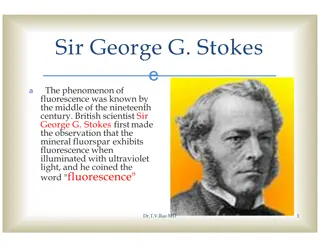
Phenomenon of Fluorescence
•
Energy Diagram
•
Rates of excitation, emission, ISC
•
Practical Issues
•
Lighting, Filters
•
Homework 2 review
Detectors for microscopy
•
Film
•
CMOS (
Complementary
metal–oxide–semiconductor
)
•
CCD (
Charge coupled device
)
•
PMT (
Photomultiplier tube
)
•
GaAsP (
Gallium arsenide
phosphide
)
•
APD (
Avalanche photodiode
)
Array of detectors, like your retina
Single point source detectors
Let’s look at an actual
example
Visualizing hearing in vivo
High speed cameras
•
Used by the military so
expensive
•
10,000 frames/sec.
•
Fastcam 1024 PCI
•
Photron, up to 100,000
fps
•
47,000 with LED
illumination and DIC
•
ProAnalyst software
•
Xcetex, Cambridge,
Mass
Actually Fastcam SA5
Nyquist criterion
•
Sampling frequency needs to be greater than twice
the frequency trying to image
•
Undersampling can result in aliasing
•
Such differences can result in distortions or
artifacts
•
Avoid the “wagon wheel” effect
Visualizing Hearing
In Vivo
•
Spontaneous otoacoustic emissions
•
In vivo SOAE 600 Hz to 60 kHz
•
In vitro hair bundle motions
<
100 Hz
•
Playing sounds 100 to 2000 Hz
•
Experimental Setup
•
High magnification DIC
microscopy
•
High speed camera 6000 fps +
•
Specialized data analysis
software
Temporal Resolution: Ultra High-
Speed Video
•
1000 fps is 1024x1024
•
6000 fps reduced to
512x256, 1024x128, etc.
•
High Power LED System-
36AD3500, Lightspeed
Technologies, Campbell,
CA
•
20/80 to 90/10 on/off
•
Fastcam SA1 (Photron,
San Diego, CA), 5400 fps
at 1024x1024
6000 fps movie played at 30 fps
Med Engineering
Seminar Last
Week
•
Lihong V. Wang
•
Working on Detector that can
go 1,000,000,000 frames/sec!
•
So we all know the problem
here
Med Engineering
Seminar Last
Week
•
Lihong V. Wang
•
Working on Detector that can
go 1,000,000,000 frames/sec!
•
So we all know the problem
here
Photomultiplier Tube (PMT)
•
Two types of
Photomultipliers
•
Side-on, most
popular due to high
performance rating
and low cost
•
Head-on
Photomultiplier Tube (PMT)
•
PMTs use electric potential to amplify electrons
•
Photons impact a phosphor screen creating
electrons
•
Electrons are multiplied by impacting other
surfaces (Dynode chain)
•
Increasing the gain increases the number of
electrons produced in a non-linear fashion
•
So increasing Gain increases signal
Photomultiplier Tube (PMT)
•
PMTs less sensitive in
the red
•
Can buy PMTs that are
more “green” sensitive
or more “red”sensitive
•
But not much difference
As with CCDs, PMTs have same
Noise problems
•
Shot noise
•
Random fluctuations in the photon population
•
Dark current
•
Noise caused by spontaneous electron formation/accumulation in
the wells (usually due to heat)
•
Readout noise
•
Grainy noise you see when you expose the chip with no light
The cost of increasing gain
•
More electrons means more noise
•
This is what causes the noise in scanning confocal
images
•
Averaging can decrease the noise
Dynamic Range
(bit depth)
•
Full well capacity/read noise
•
2^8 = 256 gray values = 8 bits, 2^10 = 1024 grays values
= 10 bits, etc
•
8 bit (video camera)
•
Your eye can detect this range, computers and printers are
therefore designed around this value
•
16 bit
•
Good to detect very dim and very bright things in the same
field of view without saturation (maxing out the range)
•
Very good for quantifying fluorescence
•
Have to convert to 8 bits for presentations
Confocal Imaging: Avalanche Photodiodes
Cindy Chiu from David Prober’s Lab, Caltech
Fluorescence Microscopy
The Ultimate in Contrast
Thus Far, have considered compound microscope, and the
microscope optics as a projection system (into eye)
•
Deliver light to the specimen
•
Image light from the specimen
•
Contrast from light absorbed,
diffracted
Transmitted light microscopy: photons out of the
microscope are some fraction of the photons in
Now, turn our attention to fluorescence, based on
the absorption and re-emission of photons
Fluorescent Dye
Dipole antenna
Delocalized electrons
Longer dipole, longer
Fluorescence
•
Easy to set up: Objective = Condenser
•
Highly specific technique, wide selection of markers
•
Detection and Identification of Proteins, Bacteria,
Viruses
•
Basics for
•
Special Techniques eg. TIRF, FRET, FRAP etc.
•
3-D imaging
•
Deconvolution
•
Structured Illumination
•
Confocal Techniques
Light sources
•
Mercury (Hg)
•
Xenon, Hg/Xe Combination
•
Laser
•
LED’s
•
Tungsten Halogen
Dye in cuvette
Blue light absorbed
Beer
’
s Law
I
out
= I
in
e
-ax
I
absorbed
= I
out
- I
in
= I
in
(1-e
-
cx
)
= extinction coefficient
For Fluorescein
~ 70,000/(cm M/liter)
A good dye must absorb light well (high extinction coef.)
Where does energy go?
Quantum Yield = light emitted/light absorbed
Q ~ 0.8 fluorescein
~ 0.3 rhodamine
Co-fluorescein
Co-TM rhodamine
Which dye is better?
1 - absorb well (high
)
2 - emit well (high Q)
Brightness ~
Q
(fluorescein 0.8 * 70,000 = 57,000)
(rhodamine 0.3 * 90,000 = 27,000)
4nsec
Go deeper to explain bleaching and background
(Jablonski diagram)
0.8 emitted
Other losses
Heat
Energy transfer
4nsec
Add in Interstate Crossing (ISC)
0.8 emitted
fluorescence
ISC
~0.03
Excited triplet
state
Phosphorescence
(usec - msec)
Triplet state is long lived.
therefore even low probability can deplete active dye
(steady state reached in ~200msec
~80-90% in triplet --> 5-10 fold dimmer)
CLSM: can have a major impact (~5 fold less throughput)
4nsec
Interstate Crossing (ISC) Problem 2: Reactive oxygen
0.8 emitted
fluorescence
ISC
~0.03
Excited triplet
state
Phosphorescence
(usec - msec)
Triplet state lifetime shortened by oxygen
(20msec if none; 0.1 usec if oxygen present
Good news: Returns dye to ground state
Bad news: Creates reactive oxygen
Aside: Phosphor Imager
ISC
High probability
Excited triplet
state
Phosphorescence
(
very
slow)
Very
slow
Accumulate triplet state (thermally stable)
“
read out
”
with scanning red laser
Gives energy for transition to singlet state
Emission of light proportional to the stored triplet
Issues in fluorescence
1. No dye is perfect < 100,000 photons total
(ISC, bleaching)
2. Every emitted photon is sacred
(NA 1.25 collects ~20%)
(clsm w/ PMT collects 0.02% - 0.3%)
3. Signal/noise limited by number of photons
Counting error N ± sqrt(N)
Image requires >200 photons/pixel
Not enough fluorescence photons?
If >200 photons/ pixel needed
Microscope records 0.02%
Need about 100,000 photons/pixel
~ lifetime of a dye
Given dwell-time of laser beam, ISC, collection efficiency
Lucky to record 1 photon/dye/scan
Every emitted photon is sacred!
Maximize throughput (filters, lenses, mirrors)
Minimize Bleaching
To reduce bleaching:
Shorten Triplet lifetime
Antibleach Agents:
Retinoids, carotinoids, glutathione
Vitamin E, N-propyl gallate
Eliminate Oxygen (scavenger, bubble N
2
)
No reactive oxygen produced
(but lengthens triplet lifetime)
Can
’
t get more light by turning up the laser:
Dye saturates as I is increased
Intense laser beam depletes dye in ground state
Pumps more dye into the triplet state
(reactive oxygen and silent)
Noise doesn
’
t saturate
Autofluorescence in cell
flavins, NADH, NADPH
Raman spectrum of water
(488nm in; 584nm out)
Optimize light collection, uniformity of illumination
High NA, Kohler illumination
N.A. and image brightness
Transmitted light
Brightness = fn (NA
2
/ magnification
2
)
Epifluorescence
Brightness = fn (NA
4
/ magnification
2
)
10x 0.5 NA is 3 times brighter than 10x 0.3NA
10x 0.5 NA is 8 times brighter than 10x 0.3NA
First Fluorescence microscope
•
Built by Henry
Seidentopf & August
Köhler (1908)
•
Used transmitted light
path
•
So dangerous that
couldn’t look through
it, needed camera
Ima
g
e
c
r
edit:
c
orpo
r
a
t
e
.
z
eiss.
c
om
“
T
echni
c
a
l
Mile
s
t
on
e
s
of
Mic
r
os
c
o
p
y
”
First epi-fluorescence
microscope
•
Designed in 1929 by German
pharmacologist Philipp Ellinger &
anatomist August Hirt
•
Used yellow barrier filter between
objective and ocular to block
reflected excitation light
•
Would be custom made, specialized
instrument for almost 40 years
Key advance dichroic mirrors!
•
Dutch scientist Bas Ploem
developed these in 1967
•
Dichromatic mirrors
converted epi-fluorescence
microscope from a tool
that could be used only by
trained specialists to a
universal and indispensable
instrument for modern
biology
Prototype of first epi-illumination fluorescence microscope that he developed in Amsterdam in the sixties
Choose filters well
Excitation
Dichroic
Emission
Optimize the light path for collection
Excitation filter:
Selectively excite dye
Emission filter:
Selectively detect dye
Dichroic Reflector:
Bounce exciting
Pass emitted
How to separate wavelengths: Interference Filters
Basic principle based on reflection from mirror
Reflection from higher index
--> 180 degree shift
(separated for clarity below)
mirror
Interference Filters
Add a layer of intermediate index
3% reflection from glass
(higher index --> 180 degree shift
(separated for clarity below)
Interference Filters are wavelength dependent
2
= 2 x
1
Destructive interference
(antireflection coating)
most light passed
4
2
1
Constructive interference
Less light passed
2
Interference filters: the movie
•
Reflect one wavelength
while passing another
•
Innovation that relatively
inexpensive to make
Link to Java Tutorial
http://www.olympusfluoview.com/theory/interferencefilters.html
Dichroic reflector
Issues:
How steep,
How efficient to excite
How efficient to collect
Dichroic reflectors tend to be characterized by the color(s) of light
that they reflect, rather than the color(s) they pass
Excitation filter:
Selectively excite dye
Emission filter:
Selectively detect dye
Dichroic Reflector:
Bounce exciting
Pass emitted
Epi - Fluorescence
(Specimen containing
green
fluorescing Fluorochrome)
Dichromatic Mirror
Emission Filter
Excitation Filter
Observation port
FL
Light
Source
Specimen containing
green
fluorescing Fluorochrome
Here is what they look like
•
Nikon
•
Olympus
Different kinds of Emission and
Excitation Filters
Reading bandpass filter spectrum
•
All have a center
wavelength
•
Guaranteed Minimum
Bandwidth (GMBW)
•
This is less than the
FWHM
•
Example 520/35 filter
(502.5-537.5)
Final Note:
Resonance Energy Transfer (non-radiative)
The Bad: Self-quenching
If dye at high concentration
“
hot-potato
”
the energy
until lost
Final Note:
Resonance Energy Transfer (non-radiative)
The Good: FRET as a molecular yardstick
Transfer of energy from one dye
to another
Depends on:
Spectral overlap
Distance
Alignment
FRET:
Optimize spectral overlap
Optimize
-- alignment of dipoles
Minimize direct excitement of the acceptor
(extra challenge for filter design)
donor
acceptor
Homework 2
The answer.
The Finitely Corrected
Compound
Microscope
Objective
Eyepiece
Objective
Mount (Flange)
150 mm
(tube length = 160mm)
B
B
A
In most finitely corrected systems, the eyepiece has to correct for the Lateral Chromatic Aberrations of the
objectives, since the intermediate image is not fully corrected.
(Note: the LCA correction is done in a brand-specific fashion)
Tube lens
(Zeiss: f=164.5mm)
Objective
Eyepiece
The Compound Microscope (infinity
corrected)
Homework 2
: Why are most modern
microscopes
“
infinity corrected
”
Hint - think of the influence of a piece of
glass
Image
Eyepiece
image
Eyepiece
Lens of eye
Image
Eyepiece
image
Eyepiece
Lens of eye
Take special case:
Glass at right angle to
second principle ray
Simplify by removing
eyepiece and eye
Image
Eyepiece
image
Take special case:
Glass at right angle to
second principle ray
Refraction of
principle rays
Image
Eyepiece
image
Eyepiece
Tube lens
Objective
“
Infinity
”
Domain
“
Infinity correction
”
provides a region in which an
optical flat will not create a zone of confusion
Lens of eye
Infinity optics creates a domain in which all rays
from same point in object are parallel
Infinity domain
Good Aspects:
•
Optical flats inserted have no
effect (shift doesn
’
t matter)
•
Magnification unchanged by
adding accessories
BUT:
•
Remember that thin lens laws no
longer apply
http://microscopy.fsu.edu/primer/anatomy/infinityintro.html
Nikon. Leica
Zeiss
Different manufacturers have elected different compromises
•
Length of objective lens
•
Diameter of objective lens
•
Focal length of tube lens
Longer tube lens focal length easier to design,
But requires larger diameter threads.
Conjugate Planes in Infinity Optics
Illumination Path
Imaging Path
Eyepiece
TubeLens
Objective
Condenser
Collector
Eye
Field Diaphragm
Specimen
Intermediate Image
Retina
Light Source
Condenser Aperture Diaphragm
Objective Back Focal Plane
Eyepoint
Fluorescent proteins
•
Proteins from marine
invertebrates
•
Can be coded in genes
and made by the
organism
•
Now come in a variety
of colors
Green Fluorescent Protein
•
First fluorescent protein
discovered and
developed for biological
use
•
Mutated for temp
stability, color and
turnover rate
•
Importance of
monomer vs dimer or
tetramer
Photoconvertible Proteins
•
Kaede, coral fluorescent protein, tetramer
•
Dendra2, from soft coral, monomer
•
UV Laser (405 nm) to convert green to red
•
ROI (Region Of Interest) allows precise targeting
www.olympusfluoview.com
www.amalgaam.co.jp
Delve into the fascinating world of fluorescence microscopy and high-speed cameras in biology through topics such as detectors for microscopy, Nyquist criterion, visualizing hearing in vivo, and temporal resolution insights. Learn about techniques, equipment, and practical considerations in utilizing these advanced tools for scientific research and analysis.

Download Presentation

Please find below an Image/Link to download the presentation.
The content on the website is provided AS IS for your information and personal use only. It may not be sold, licensed, or shared on other websites without obtaining consent from the author. Download presentation by click this link. If you encounter any issues during the download, it is possible that the publisher has removed the file from their server.
E N D
Presentation Transcript
Biology 177: Principles of Modern Microscopy Lecture 06: Fluorescence Microscopy
Lecture 6: Fluorescence Microscopy Detectors for Microscopy, Part 2 CMOS, PMT and APD Phenomenon of Fluorescence Energy Diagram Rates of excitation, emission, ISC Practical Issues Lighting, Filters Homework 2 review
Detectors for microscopy Film CMOS (Complementary metal oxide semiconductor) CCD (Charge coupled device) PMT (Photomultiplier tube) GaAsP (Gallium arsenide phosphide) APD (Avalanche photodiode) Array of detectors, like your retina Single point source detectors
Lets look at an actual example Visualizing hearing in vivo
High speed cameras Used by the military so expensive 10,000 frames/sec. Fastcam 1024 PCI Photron, up to 100,000 fps 47,000 with LED illumination and DIC ProAnalyst software Xcetex, Cambridge, Mass Actually Fastcam SA5
Nyquist criterion Sampling frequency needs to be greater than twice the frequency trying to image Undersampling can result in aliasing Such differences can result in distortions or artifacts Avoid the wagon wheel effect
Visualizing Hearing In Vivo Spontaneous otoacoustic emissions In vivo SOAE 600 Hz to 60 kHz In vitro hair bundle motions < 100 Hz Playing sounds 100 to 2000 Hz Experimental Setup High magnification DIC microscopy High speed camera 6000 fps + Specialized data analysis software Speaker Water- filled tube Specimen Glass bottom dish
Temporal Resolution: Ultra High- Speed Video 1000 fps is 1024x1024 6000 fps reduced to 512x256, 1024x128, etc. High Power LED System- 36AD3500, Lightspeed Technologies, Campbell, CA 20/80 to 90/10 on/off Fastcam SA1 (Photron, San Diego, CA), 5400 fps at 1024x1024
Med Engineering Seminar Last Week Lihong V. Wang Working on Detector that can go 1,000,000,000 frames/sec! So we all know the problem here
Med Engineering Seminar Last Week Lihong V. Wang Working on Detector that can go 1,000,000,000 frames/sec! So we all know the problem here
Photomultiplier Tube (PMT) Two types of Photomultipliers Side-on, most popular due to high performance rating and low cost Head-on
Photomultiplier Tube (PMT) PMTs use electric potential to amplify electrons Photons impact a phosphor screen creating electrons Electrons are multiplied by impacting other surfaces (Dynode chain) Increasing the gain increases the number of electrons produced in a non-linear fashion So increasing Gain increases signal
Photomultiplier Tube (PMT) PMTs less sensitive in the red Can buy PMTs that are more green sensitive or more red sensitive But not much difference
As with CCDs, PMTs have same Noise problems Shot noise Random fluctuations in the photon population Dark current Noise caused by spontaneous electron formation/accumulation in the wells (usually due to heat) Readout noise Grainy noise you see when you expose the chip with no light
The cost of increasing gain More electrons means more noise This is what causes the noise in scanning confocal images Averaging can decrease the noise
Dynamic Range (bit depth) Full well capacity/read noise 2^8 = 256 gray values = 8 bits, 2^10 = 1024 grays values = 10 bits, etc 8 bit (video camera) Your eye can detect this range, computers and printers are therefore designed around this value 16 bit Good to detect very dim and very bright things in the same field of view without saturation (maxing out the range) Very good for quantifying fluorescence Have to convert to 8 bits for presentations
Confocal Imaging: Avalanche Photodiodes Cindy Chiu from David Prober s Lab, Caltech
Fluorescence Microscopy The Ultimate in Contrast
Thus Far, have considered compound microscope, and the microscope optics as a projection system (into eye) Deliver light to the specimen Image light from the specimen Contrast from light absorbed, diffracted
Transmitted light microscopy: photons out of the microscope are some fraction of the photons in Now, turn our attention to fluorescence, based on the absorption and re-emission of photons Fluorescent Dye Dipole antenna Delocalized electrons Longer dipole, longer
Fluorescence Easy to set up: Objective = Condenser Highly specific technique, wide selection of markers Detection and Identification of Proteins, Bacteria, Viruses Basics for Special Techniques eg. TIRF, FRET, FRAP etc. 3-D imaging Deconvolution Structured Illumination Confocal Techniques
Light sources Mercury (Hg) Xenon, Hg/Xe Combination Laser LED s Tungsten Halogen
A good dye must absorb light well (high extinction coef.) Dye in cuvette Blue light absorbed Beer s Law Iout = Iin e-ax Iabsorbed = Iout - Iin = Iin(1-e- cx) = extinction coefficient 490nm Light absorbed For Fluorescein ~ 70,000/(cm M/liter) Wavelength
Where does energy go? Green light emitted Blue light absorbed Quantum Yield = light emitted/light absorbed Q ~ 0.8 fluorescein Stokes Shift ~ 0.3 rhodamine 490nm 520nm
Co-fluorescein Co-TM rhodamine
Which dye is better? 1 - absorb well (high ) 2 - emit well (high Q) Brightness ~ Q (fluorescein 0.8 * 70,000 = 57,000) (rhodamine 0.3 * 90,000 = 27,000)
Go deeper to explain bleaching and background (Jablonski diagram) 4nsec Other losses Heat Energy transfer 0.8 emitted
Add in Interstate Crossing (ISC) ISC ~0.03 Excited triplet state 0.8 emitted fluorescence 4nsec Phosphorescence (usec - msec) Triplet state is long lived. therefore even low probability can deplete active dye (steady state reached in ~200msec ~80-90% in triplet --> 5-10 fold dimmer) CLSM: can have a major impact (~5 fold less throughput)
Interstate Crossing (ISC) Problem 2: Reactive oxygen ISC ~0.03 Excited triplet state 0.8 emitted fluorescence 4nsec Phosphorescence (usec - msec) Triplet state lifetime shortened by oxygen (20msec if none; 0.1 usec if oxygen present Good news: Returns dye to ground state Bad news: Creates reactive oxygen
Aside: Phosphor Imager ISC High probability Excited triplet state Very slow Phosphorescence (very slow) Accumulate triplet state (thermally stable) read out with scanning red laser Gives energy for transition to singlet state Emission of light proportional to the stored triplet
Issues in fluorescence 1. No dye is perfect < 100,000 photons total (ISC, bleaching) 2. Every emitted photon is sacred (NA 1.25 collects ~20%) (clsm w/ PMT collects 0.02% - 0.3%) 3. Signal/noise limited by number of photons Counting error N sqrt(N) Image requires >200 photons/pixel
Not enough fluorescence photons? If >200 photons/ pixel needed Microscope records 0.02% Need about 100,000 photons/pixel ~ lifetime of a dye Given dwell-time of laser beam, ISC, collection efficiency Lucky to record 1 photon/dye/scan Every emitted photon is sacred! Maximize throughput (filters, lenses, mirrors) Minimize Bleaching
To reduce bleaching: Shorten Triplet lifetime Antibleach Agents: Retinoids, carotinoids, glutathione Vitamin E, N-propyl gallate Eliminate Oxygen (scavenger, bubble N2) No reactive oxygen produced (but lengthens triplet lifetime)
Cant get more light by turning up the laser: Dye saturates as I is increased Intense laser beam depletes dye in ground state Pumps more dye into the triplet state (reactive oxygen and silent) Noise doesn t saturate Autofluorescence in cell flavins, NADH, NADPH Raman spectrum of water (488nm in; 584nm out)
Optimize light collection, uniformity of illumination High NA, Kohler illumination
N.A. and image brightness N.A. = sin Transmitted light Brightness = fn (NA2 / magnification2) 10x 0.5 NA is 3 times brighter than 10x 0.3NA Epifluorescence Brightness = fn (NA4 / magnification2) 10x 0.5 NA is 8 times brighter than 10x 0.3NA
First Fluorescence microscope Built by Henry Seidentopf & August K hler (1908) Used transmitted light path So dangerous that couldn t look through it, needed camera Image credit: corporate.zeiss.com Technical Milestones of Microscopy
First epi-fluorescence microscope Designed in 1929 by German pharmacologist Philipp Ellinger & anatomist August Hirt Used yellow barrier filter between objective and ocular to block reflected excitation light Would be custom made, specialized instrument for almost 40 years
Key advance dichroic mirrors! Dutch scientist Bas Ploem developed these in 1967 Dichromatic mirrors converted epi-fluorescence microscope from a tool that could be used only by trained specialists to a universal and indispensable instrument for modern biology Prototype of first epi-illumination fluorescence microscope that he developed in Amsterdam in the sixties
Choose filters well Excitation Dichroic Emission Optimize the light path for collection
Emission filter: Selectively detect dye Dichroic Reflector: Bounce exciting Pass emitted Excitation filter: Selectively excite dye
How to separate wavelengths: Interference Filters Basic principle based on reflection from mirror mirror Reflection from higher index --> 180 degree shift (separated for clarity below)
Interference Filters Add a layer of intermediate index 3% reflection from glass (higher index --> 180 degree shift (separated for clarity below) Less light passed Constructive interference 2 Note: thickness of layer in terms of wavelength
Interference Filters are wavelength dependent 2 = 2 x 1 1 Less light passed Constructive interference 2 2 most light passed Destructive interference (antireflection coating) 4 Same thickness is smaller in terms of wavelength for 2
Interference filters: the movie Reflect one wavelength while passing another Innovation that relatively inexpensive to make Link to Java Tutorial http://www.olympusfluoview.com/theory/interferencefilters.html
Dichroic reflector Issues: How steep, How efficient to excite How efficient to collect Dichroic reflectors tend to be characterized by the color(s) of light that they reflect, rather than the color(s) they pass
Emission filter: Selectively detect dye Dichroic Reflector: Bounce exciting Pass emitted Excitation filter: Selectively excite dye
Epi - Fluorescence (Specimen containing green fluorescing Fluorochrome) Observation port Excitation Filter Emission Filter FL Light Source Dichromatic Mirror Specimen containing green fluorescing Fluorochrome


")
")
")


")


")


")
 Problem 2: Reactive oxygen")