Microwave Equipments
The Antenna and Microwave Laboratory at Babol Noshirvani University of Technology in Iran provides insights into required equipment, radiation pattern measurements, transmitter and receiver setups, and the use of a spectrum analyzer. Various components such as antennas, modulators, oscillators, and more are discussed in detail.

Download Presentation

Please find below an Image/Link to download the presentation.
The content on the website is provided AS IS for your information and personal use only. It may not be sold, licensed, or shared on other websites without obtaining consent from the author.If you encounter any issues during the download, it is possible that the publisher has removed the file from their server.
You are allowed to download the files provided on this website for personal or commercial use, subject to the condition that they are used lawfully. All files are the property of their respective owners.
The content on the website is provided AS IS for your information and personal use only. It may not be sold, licensed, or shared on other websites without obtaining consent from the author.
E N D
Presentation Transcript
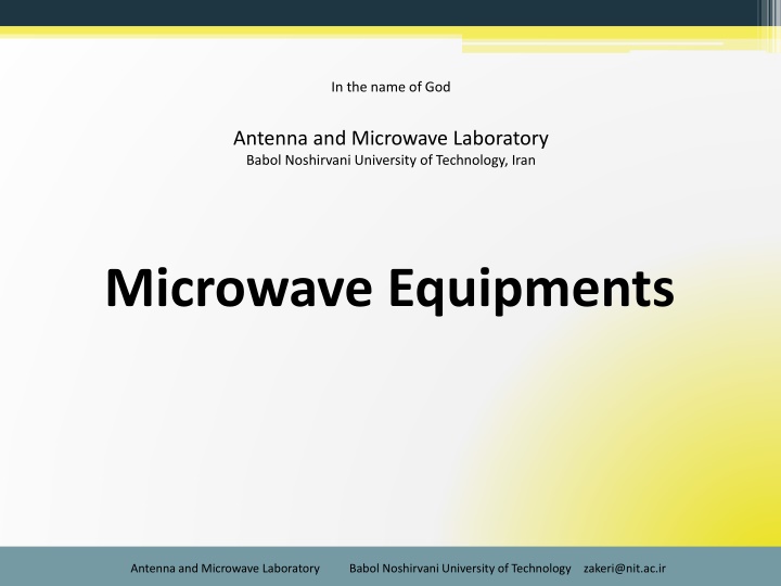
In the name of God Antenna and Microwave Laboratory Babol Noshirvani University of Technology, Iran Microwave Equipments Antenna and Microwave Laboratory Babol Noshirvani University of Technology zakeri@nit.ac.ir
1 The required equipment for antenna measurements include: source antenna known pattern, desired polarization, suitable beamwidth often horn antennas, or a dipole antenna with a parabolic reflector Transmitting System stable known power, tunable (selectable) frequency, stable frequency A receiver system This determines how much power is received by the test antenna A positioning system This system is used to rotate the test antenna relative to the source antenna, to measure the radiation pattern as a function of angle. Absorber To simulate a free space for antenna Computer Absorbers Test Antenna Source Antenna Positioning System Receiver Transmitter Antenna and Microwave Laboratory Babol Noshirvani University of Technology zakeri@nit.ac.ir
Radiation Pattern Measurement Setup: 3 Antenna and Microwave Laboratory Babol Noshirvani University of Technology zakeri@nit.ac.ir
1 Antenna and Microwave Laboratory Babol Noshirvani University of Technology zakeri@nit.ac.ir
Transmitter PIN Modulator PIN Diode (Modulator) Tx Antenna Isolator Gunn Oscillator 10mW 9.40 GHz. To avoid feedback Avoid looking directly into end of radiating Antenna. Or: Tx Antenna Synthesized Sweeper Antenna and Microwave Laboratory Babol Noshirvani University of Technology zakeri@nit.ac.ir
Receiver Amplifier Detector (demodulator) Rotator Rx (test) Antenna Displayer or: Spectrum Analyzer Displayer Rx (test) Antenna Antenna and Microwave Laboratory Babol Noshirvani University of Technology zakeri@nit.ac.ir
Radiation Pattern Measurement Setup: Antenna and Microwave Laboratory Babol Noshirvani University of Technology zakeri@nit.ac.ir
2 Spectrum Analyzer 8562A Frequency Range: 1KHz 22GHz Antenna and Microwave Laboratory Babol Noshirvani University of Technology zakeri@nit.ac.ir
3 Another Oscilloscope ??? Like an oscilloscope Oscilloscope in time domain Spectrum analyzer in frequency domain (selectable) Is Frequency Domain Better? In time domain, all frequency components of signals are summed together In frequency domain, complex signals are separated into their frequency components Antenna and Microwave Laboratory Babol Noshirvani University of Technology zakeri@nit.ac.ir
4 What does SA do? Processes the signal Displays the spectral content of the input signal within a selected range of frequencies i.e., signal power(db) versus frequency Measures frequency, power, harmonic content, modulation, spurs, and noise, etc Antenna and Microwave Laboratory Babol Noshirvani University of Technology zakeri@nit.ac.ir
5 Types of RF Spectrum Analyzer Two common ways to measure RF signals: Capture time domain signals information Digitizes time domain signal (digital sampling) Perform Fourier transform Fast, but limits in frequency range, sensitivity Fourier Transform: Swept-Tuned or Swept-Toned: Sweep across frequency range Display the frequency of interest Large frequency range Widely used Antenna and Microwave Laboratory Babol Noshirvani University of Technology zakeri@nit.ac.ir
6 Three Primary Function Keys Frequency (Hz) Amplitude (Abs dBm, Rel dB) Span (Hz) -> (how big the window we want to view) Antenna and Microwave Laboratory Babol Noshirvani University of Technology zakeri@nit.ac.ir
7 Principals of a Spectrum Analyzer 13 Antenna and Microwave Laboratory Babol Noshirvani University of Technology zakeri@nit.ac.ir
8 Typical Output Displayed Antenna and Microwave Laboratory Babol Noshirvani University of Technology zakeri@nit.ac.ir
9 Typical Output Displayed Antenna and Microwave Laboratory Babol Noshirvani University of Technology zakeri@nit.ac.ir
10 Typical Output Displayed Antenna and Microwave Laboratory Babol Noshirvani University of Technology zakeri@nit.ac.ir
11 Synthesized Sweeper 8341B Frequency Range: 10MHz 20GHz Antenna and Microwave Laboratory Babol Noshirvani University of Technology zakeri@nit.ac.ir
12 Vector Network Analyzer (VNA) Antenna and Microwave Laboratory Babol Noshirvani University of Technology zakeri@nit.ac.ir
13 Microwave Connectors Most coaxial cables and connectors in common use have a 50 characteristic impedance, with an exception being the 75 cable used in television systems. The reasoning behind these choices is that: an air-filled coaxial line has minimum attenuation for a characteristic impedance of about 77 (D. Pozar, Microwave Engineering, 4th edition, problem 2.27, page: 93 ) while maximum power capacity occurs for a characteristic impedance of about 30 A 50 characteristic impedance thus represents a compromise between minimum attenuation and maximum power capacity. Other requirements for coaxial connectors include: low SWR, higher-order-mode free operation at a high frequency, high repeatability after a connect disconnect cycle, mechanical strength. Antenna and Microwave Laboratory Babol Noshirvani University of Technology zakeri@nit.ac.ir
14 Microwave Connectors several types of commonly used coaxial connectors and adapters: SMA Type-N, TNC APC-7 2.4 mm It is highly recommended to visit http://www.microwaves101.com/encyclopedia/connectors.cfm for more information. Also the webpage is available in the folder) Antenna and Microwave Laboratory Babol Noshirvani University of Technology zakeri@nit.ac.ir
15 Software training Dipole Antenna Design in CST Antenna and Microwave Laboratory Babol Noshirvani University of Technology zakeri@nit.ac.ir
16 Dipole Antenna Design in CST The total input impedance for l = /2 is equal to (infinite small radius): Zin =73+j42.5 To reduce the imaginary part of the input impedance to zero, the antenna is matched or reduced in length until the reactance vanishes. The latter is most commonly used in practice for half-wavelength dipoles. Depending on the radius of the wire: length of the dipole for first resonance is about l =0.47 to 0.48 ; Thin wires closer the length to 0.48 Increasing of wire radius decreasing of length Standing Wave Antenna Antenna and Microwave Laboratory Babol Noshirvani University of Technology zakeri@nit.ac.ir
17 Dipole Antenna Design in CST The dipole length has been adjusted to tune the antenna to 1 GHz. Parameter Value Description 150 mm (0.5 ) L Dipole length 6 mm (0.02 ) Gap Feeding gap of the antenna 3 mm (0.01 ) r radius of the conductor Z0 ? Port impedance Antenna and Microwave Laboratory Babol Noshirvani University of Technology zakeri@nit.ac.ir
18 The Electric field intensity of a dipole antenna at its resonant frequency Antenna and Microwave Laboratory Babol Noshirvani University of Technology zakeri@nit.ac.ir