S-Parameter Measurements in Microwave Engineering
Prof. David R. Jackson
Dept. of ECE
N
o
t
e
s
1
7
ECE 5317-6351
ECE 5317-6351
Microwave Engineering
Microwave Engineering
F
a
l
l
2
0
1
9
S
-Parameter
Measurements
1
Adapted from notes by
Prof. Jeffery T. Williams
S
-parameters are typically measured, at microwave
frequencies, with a network analyzer (NA).
These instruments have found wide, almost universal, application since
the mid to late 1970’s.
Vector* network analyzer:
Magnitudes
and
phases of the
S
parameters are measured.
Scalar network analyzer:
Only the magnitudes of the
S
-parameters are measured.
2
S
S
-Parameter Measurements
-Parameter Measurements
Most NA’s measure 2-port parameters. Some measure 4 and 6 ports.
* The
S
parameters are really complex numbers, not vectors, but this is the
customary name. There is an analogy between complex numbers and 2D vectors.
3
A Vector Network Analyzer (VNA) is usually used to measure
S
parameters.
N
o
t
e
:
If there are more than 2 ports, we measure different pairs
of ports separately with a 2-port VNA.
S
S
-Parameter Measurements (cont.)
-Parameter Measurements (cont.)
4
S
S
-Parameter Measurements (cont.)
-Parameter Measurements (cont.)
Error boxes contain effects
of test cables, connectors, couplers,…
5
S
S
-Parameter Measurements (cont.)
-Parameter Measurements (cont.)
6
S
S
-Parameter Measurements (cont.)
-Parameter Measurements (cont.)
Embedded inside measured ABCD matrix
De-embedded
This is called “de-embedding”.
7
Assume error boxes are reciprocal (symmetric matrices)
S
S
-Parameter Measurements (cont.)
-Parameter Measurements (cont.)
“
S
h
o
r
t
,
o
p
e
n
,
m
a
t
c
h
”
c
a
l
i
b
r
a
t
i
o
n
p
r
o
c
e
d
u
r
e
Calibration loads
Calibration
Calibration
Recall from Notes 16:
8
These loads are connected to the end of the cable from the VNA.
“
T
h
r
u
-
R
e
f
l
e
c
t
-
L
i
n
e
(
T
R
L
)
”
c
a
l
i
b
r
a
t
i
o
n
p
r
o
c
e
d
u
r
e
Calibration (cont.)
Calibration (cont.)
9
This is an improved calibration method that involves three types
of connections:
1)
The “thru” connection, in which port 1 is directly connected to port 2.
2)
The “reflect” connection, in which a load with an (ideally) large (but not
necessarily precisely known) reflection coefficient is connected.
3)
The “line” connection, in which a length of matched transmission line
(with an unknown length) is connected between ports 1 and 2.
The advantage of the TRL calibration is that is does not require precise short,
open, and matched loads.
This method is discussed in the Pozar book (pp. 193-196).
Discontinuities
Discontinuities
10
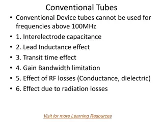
In microwave engineering, discontinuities are often represented
by pi or tee networks.
Sometimes the pi or tee network reduces to a singe series or
shunt element.
For waveguide systems, the TEN is used to represent the
waveguide.
Discontinuities: Rectangular Waveguide
Discontinuities: Rectangular Waveguide
11
12
Discontinuities: RWG (cont.)
Discontinuities: RWG (cont.)
Discontinuities: Microstrip
Discontinuities: Microstrip
13
N
o
t
e
:
For a good equivalent circuit,
the element values are fairly stable over a wide range of frequencies.
Z
Z
-Parameter Extraction
-Parameter Extraction
Assume a reciprocal and
symmetrical
waveguide or
transmission-line discontinuity.
Examples
W
a
v
e
g
u
i
d
e
p
o
s
t
M
i
c
r
o
s
t
r
i
p
g
a
p
We want to find
Z
1
and
Z
2
to
model the
discontinuity.
14
TEN
N
o
t
e
:
We could also use a
pi network if we wish.
Plane of symmetry (POS)
POS
Z
Z
-Parameter Extraction (cont.)
-Parameter Extraction (cont.)
15
The
Z
2
element is split in two:
Assume that we place a
short
or an
open
along the plane of symmetry.
Z
Z
-Parameter Extraction (cont.)
-Parameter Extraction (cont.)
16
The short or open can be realized by using odd-mode or even-mode excitation.
Z
Z
-Parameter Extraction (cont.)
-Parameter Extraction (cont.)
Odd mode excitation
Even mode excitation
17
Even/odd-mode analysis is very useful in analyzing devices (e.g., using HFSS).
Z
Z
-Parameter Extraction (cont.)
-Parameter Extraction (cont.)
18
Odd mode voltage waves
Even mode voltage waves
Z
Z
-Parameter Extraction (cont.)
-Parameter Extraction (cont.)
19
Hence we have:
De-embeding of a Line Length
De-embeding of a Line Length
We wish the know the reflection coefficient of a 1-port device under test (DUT),
but the DUT is not assessable directly – it has an extra length of transmission line
connected to it (whose length may not be known).
20
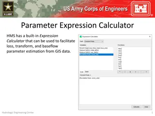
S-Parameter measurements in microwave engineering are typically conducted using a Vector Network Analyzer (VNA) to analyze the behavior of devices under test (DUT) at microwave frequencies. These measurements involve the use of error boxes, calibration techniques, and de-embedding processes to extract accurate S-Parameter values for effective analysis and design.

Download Presentation

Please find below an Image/Link to download the presentation.
The content on the website is provided AS IS for your information and personal use only. It may not be sold, licensed, or shared on other websites without obtaining consent from the author.If you encounter any issues during the download, it is possible that the publisher has removed the file from their server.
You are allowed to download the files provided on this website for personal or commercial use, subject to the condition that they are used lawfully. All files are the property of their respective owners.
The content on the website is provided AS IS for your information and personal use only. It may not be sold, licensed, or shared on other websites without obtaining consent from the author.
E N D
Presentation Transcript
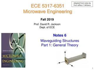
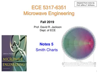
Adapted from notes by Prof. Jeffery T. Williams ECE 5317-6351 Microwave Engineering Fall 2019 Prof. David R. Jackson Dept. of ECE Notes 17 S-Parameter Measurements 1
S-Parameter Measurements S-parameters are typically measured, at microwave frequencies, with a network analyzer (NA). These instruments have found wide, almost universal, application since the mid to late 1970 s. Vector* network analyzer: Magnitudes and phases of the S parameters are measured. Scalar network analyzer: Only the magnitudes of the S-parameters are measured. Most NA s measure 2-port parameters. Some measure 4 and 6 ports. * The S parameters are really complex numbers, not vectors, but this is the customary name. There is an analogy between complex numbers and 2D vectors. 2
S-Parameter Measurements (cont.) A Vector Network Analyzer (VNA) is usually used to measure S parameters. Device Under Test (DUT) Port 1 Port 2 Note: If there are more than 2 ports, we measure different pairs of ports separately with a 2-port VNA. 3
S-Parameter Measurements (cont.) Vector Network Analyzer Port 1 Measurement plane 1 Port 2 Measurement plane 2 1a 2 a 1b 2b Device under test (DUT) Test cables 4
S-Parameter Measurements (cont.) We want to measure [S] for DUT m a b m a b 2 m Error Box B Port 1 Port 2 Error Box A 1 m DUT 2 1 Meas.plane 2 Meas.plane 1 Ref.plane Ref.plane Error boxes contain effects of test cables, connectors, couplers, MEAS A C B D A B A C B D A C B D A C B D 5
S-Parameter Measurements (cont.) MEAS A C B D A B A C B D A C B D A C B D MEAS A B A C B D A C B D A C B D A C B D = Embedded inside measured ABCD matrix De-embedded 1 1 MEAS A B A C B D A C B D A C B D A C B D = 6
S-Parameter Measurements (cont.) S A B S S Measurement plane A Measurement plane B Error box A DUT Error box B Assume error boxes are reciprocal (symmetric matrices) A B We need to calibrate to find " " . S S and S A B If are known we can extract from measurements. S S and This is called de-embedding . 7
Calibration Short, open, match calibration procedure Connect Z0 SC OC S = = = 1 1 0 L L L Short Open Match Error box Calibration loads These loads are connected to the end of the cable from the VNA. ( 1 ) 2 S + Recall from Notes 16: 21 S = m S S measurements: 3 11 11 SC 21 12 S S 22 m m m = + ( , , ) S S S S L ( 1 ) 11 in 2 1 S 11 11 11 SC OC match S 22 L 21 S = + m S S unknowns: 3 11 11 OC ( ) 22 , , S S S = m S S 11 21 22 11 11 match 8
Calibration (cont.) Thru-Reflect-Line (TRL) calibration procedure This is an improved calibration method that involves three types of connections: 1) The thru connection, in which port 1 is directly connected to port 2. 2) The reflect connection, in which a load with an (ideally) large (but not necessarily precisely known) reflection coefficient is connected. 3) The line connection, in which a length of matched transmission line (with an unknown length) is connected between ports 1 and 2. The advantage of the TRL calibration is that is does not require precise short, open, and matched loads. This method is discussed in the Pozar book (pp. 193-196). 9
Discontinuities In microwave engineering, discontinuities are often represented by pi or tee networks. Sometimes the pi or tee network reduces to a singe series or shunt element. For waveguide systems, the TEN is used to represent the waveguide. 10
Discontinuities: Rectangular Waveguide Inductive iris or strip Capacitive iris or strip Resonant iris 11
Discontinuities: RWG (cont.) Z Z 01 02 E plane step Z Z 01 02 H plane step 12
Discontinuities: Microstrip Z Z 0 C 0 C s C C Z Z Z Z p p 0 0 0 0 L L Z Z Z Z C 02 01 01 02 Note: For a good equivalent circuit, the element values are fairly stable over a wide range of frequencies. 13
Z-Parameter Extraction Assume a reciprocal and symmetrical waveguide or transmission-line discontinuity. T Examples g T Microstrip gap Waveguide post We want to find Z1 and Z2to model the discontinuity. = = Z Z Z Z Z Discontinuity model 1 11 21 2 21 T T 1 Z 1 Z Z Z Note: Z 0 0 2 We could also use a pi network if we wish. TEN 14
Z-Parameter Extraction (cont.) T T 1 Z 1 Z Z Z Z 0 0 2 Plane of symmetry (POS) The Z2 element is split in two: POS T T 1Z 1Z 0 Z 0 Z 2Z 2Z 2 2 15
Z-Parameter Extraction (cont.) Assume that we place a short or an open along the plane of symmetry. T T POS Z Z 1 1 Z Z Short 2Z 2Z 0 0 2 2 = = SC SC L SC L L Z Z Z Z Z Z SC L 1 1 POS Z Z 1 1 2Z 2Z Open Z Z 2 2 0 0 = = + OC + 1 OC L L Z 2 Z Z Z Z 2 Z 2 OC Z Z OC L L 1 2 1 2 ( ) = = SC L OC L SC L , Z Z Z Z Z 1 2 16
Z-Parameter Extraction (cont.) The short or open can be realized by using odd-mode or even-mode excitation. 1V 1V Z Z 0 0 Port 2 Port 1 Incident voltage waves + 1 1 Odd mode excitation + 1 + 1 Even mode excitation Even/odd-mode analysis is very useful in analyzing devices (e.g., using HFSS). 17
Z-Parameter Extraction (cont.) 1V 1V Z Z 0 0 Port 2 Port 1 SC 11 S Odd mode voltage waves + SC 11 SC 11 1 1 S S = SC L Z Z 0 1V + 1V Z Z 0 0 Port 1 Port 2 OC 11 S Even mode voltage waves + OC 11 OC 11 S 1 1 S = OC L Z Z 0 18
Z-Parameter Extraction (cont.) Discontinuity model T T 1 Z 1 Z Z Z Z 0 0 2 Hence we have: + SC 11 SC 11 1 1 S S = Z Z 1 0 + + OC 11 OC 11 S SC 11 SC 11 1 1 1 1 1 2 S S S = Z Z Z 2 0 0 19
De-embeding of a Line Length We wish the know the reflection coefficient of a 1-port device under test (DUT), but the DUT is not assessable directly it has an extra length of transmission line connected to it (whose length may not be known). DUT 11 S m S j j l ij = i i l Recall: S S e e 11 ij L = = l l L i j = = = j i j = MEAS 11 S DUT 11 S 2 j L e DUT Meas. plane Ref. plane ( ) + = = DUT 11 S MEAS, SC 11 S 2 2 j L j L 1 1/ e e Replace DUT with short circuit 1 = DUT 11 S MEAS,DUT 11 S + = DUT 11 S MEAS,DUT 11 S 2 j L e MEAS,SC 11 S 20


")
")
")
")
")

")


")


")
")
")
")
")