ANALOG AND DIGITAL ELECTRONICS 21CS33


ANALOG AND DIGITAL ELECTRONICS
21
CS33
1
MODULE-5
Registers and Counters
2
Books Referred/Source
•
Charles H Roth and Larry L Kinney, Analog and Digital Electronics,
Cengage Learning,2019
•
Charles H Roth and Larry L Kinney, Fundamental of Logic Design,
Cengage Learning, 2017.
•
Donald P Leach, Albert Paul Malvino & Goutam Saha: Digital
Principles and Applications, 7
th
Edition, Tata McGraw Hill, 2015
•
Anil K. Maini: Digital Electronics Principles, Devices and
Applications, 2007, John Wiley & Sons, Ltd.
•
Thomas L. Floyd: Digital Fundamentals, 9th Edition., Pearson
International Edition.
•
M. Morris Mano, Michael D. Ciletti : Digital Design With an
Introduction to the Verilog HDL, 5
th
Edition, Pearson Education, Inc.
•
Ronald J. Tocci, Neal S. Widmer, Gregory L. Moss: Digital systems :
principles and applications—10
th
Edition, Pearson Education
International
3
Objectives
•
Explain the operation of
registers
. Show how to transfer data between registers
using a tri-state bus.
•
Explain the operation of
shift registers
, show how to build them using flip-flops,
and analyze their operation. Construct a timing diagram for a shift register.
•
Explain the operation of
binary counters
, show how to build them using flip-flops
and gates, and analyze their operation.
•
Given the
present state and desired next state of a flip-flop
, determine the
required flip-flop inputs.
•
Given the desired
counting sequence
for a counter.
•
Construct a
timing diagram
for a counter by tracing signals through the circuit.
•
Given a sequential circuit, write the
next-state equations for the flip-flops
and
derive the
state graph or state table
. Using the state graph, determine the state
sequence and output sequence for a given input sequence.
•
Explain the difference between a
Mealy machine and a Moore machine
.
•
Given a state table, construct the
corresponding state graph
, and conversely.
•
Analyze a
sequential circuit by signal tracing
.
4
Introduction
Each flip-flop can store one bit of information
A register consists of a
group of flip-flops with a
common clock input.
Registers are commonly used to
store and shift
binary data.
Counters are another simple type of sequential circuit.
A counter is usually constructed from
two or more flip-flops
which
change states in a prescribed sequence
when input pulses
are received.
5
Registers and Register Transfers
•
4-Bit D Flip-Flop Registers with Data, Load, Clear, and
Clock Inputs
6
When
Load = 0
, the register is not clocked, and it holds its present value
When
Load = 1
, the clock signal (Clk) is transmitted to the flip-flop clock inputs
and the data applied to the D
inputs will be loaded into the flip-flops on the
falling edge of the clock.
Registers and Register Transfers
•
4-Bit D Flip-Flop Registers with Data, Load, Clear, and
Clock Inputs
7
If the Q outputs are 0000 (Q3 = Q2 = Q1 = Q0 = 0) and the data inputs are 1101
(D3 = 1, D2 = 1, D1 = 0 and D0 = 1),
after the falling edge of the clock
Q will change
from 0000 to 1101 as indicated.
Registers and Register Transfers
•
If flip-flops with clock enable are available
8
When
Load = 0
, the clock is disabled and the register holds its data.
When
Load is 1
, the clock is enabled, and the data applied to the D inputs will be
loaded into the flip-flops, following the falling edge of the clock
Registers and Register Transfers
•
A symbol for the
4-bit register
using bus notation for
the
D inputs
and
Q outputs
.
9
Registers and Register Transfers
•
Data Transfer Between Registers
10
Figure shows how data can be transferred from the output of one of two
registers into a third register using tri-state buffers.
Registers and Register Transfers
•
Data Transfer Between Registers
•
If
En = 1 and Load = 1
, the output of register A is enabled
onto the tri-state bus and the data in register A will be
stored in Q after the rising edge of the clock.
•
If
En = 0 and Load = 1
, the output of register B will be
enabled onto the tri-state bus and stored in Q after the
rising edge of the clock.
11
Registers and Register Transfers
•
Logic Diagram for 8-Bit Register with Tri-State Output
12
Figure (a) shows an integrated circuit register that contains eight D flip-flops
with tri-state buffers at the flip-flop outputs. These buffers are
enabled when
En = 0.
A symbol for this 8-bit register is shown in Figure (b).
Registers and Register Transfers
•
Data Transfer Using a Tri-State Bus
13
Figure shows how data can be transferred
from one of four 8-bit registers into
one of two other registers.
8 bits of data are transferred in parallel from register A, B, C, or D to register G
or H or both.
Registers and Register Transfers
Data Transfer Using a Tri-State Bus
•
The operation as follows:
If EF = 00, A is stored in G (or H).
If EF = 01, B is stored in G (or H).
If EF = 10, C is stored in G (or H).
If EF = 11, D is stored in G (or H).
If
LdG = 1
, these signals on the bus are loaded into
register G after the rising clock edge or into register H if
LdH = 1.
14
Parallel Adder with Accumulator
•
In computer circuits, it is frequently desirable to store
one
number
in a
register of flip-flops
(called an accumulator)
and add a
second number
to it, leaving the result stored
in the accumulator.
•
To build a parallel adder with an accumulator
is to add a
register
to the full adder (FA).
15
Parallel Adder with Accumulator
•
n-Bit Parallel Adder with Accumulator
16
X = xn . . . x2x1 is stored in the accumulator
Y= yn . . . y2 y1 is applied to the full adder inputs,
The sum of X and Y appears at the adder outputs
Add signal (Ad) is used to load the adder outputs into the accumulator flip-
flops on the rising clock edge
Parallel Adder with Accumulator
Before addition can take place, the accumulator must be
loaded with X.
This can be accomplished in
two ways
:
Clear the accumulator
Add multiplexers at the accumulator inputs
Clear the accumulator
using the asynchronous clear inputs on the
flip-flops, and then put the X data on the Y inputs to the adder and
add to the accumulator in the normal way.
17
Parallel Adder with Accumulator
•
Add multiplexers at the accumulator inputs:
So that we
could select either the Y input data or the adder output to
load into the accumulator.
18
Shift Registers
A shift register is a register in which binary
data can be
stored
, and this data can be
shifted to the left or right
when a shift signal is applied.
Bits shifted out one end of the register may be lost, or if
the shift register is of cyclic type, bits shifted out one end
are shifted back in the other end.
19
Shift Registers
•
TYPES OF REGISTERS
20
Shift Registers
•
Right-Shift Register
21
When
Shift =1
, the clock is enabled and shifting occurs on the rising clock edge.
Shift = 0
, no shifting and No changed in flip flop.
The serial input (SI) is loaded into the first flip-flop (Q3) by the rising edge of the
clock.
At the same time, the
output of the first flip-flop is loaded into the second flip-
flop
, the
output of the second flip-flop is loaded into the third flip-flop
, and the
output of the third flip-flop is loaded into the last
flip-flop
Shift Registers
•
Right-Shift Register
22
•
Shift register initially
contains 0101.
•
The
serial input (SI)
sequence is 1, 1, 0, 1.
•
The sequence of shift
register states is 0101,
1010, 1101, 0110, 1011.
Shift Registers
•
Example: Show how a number 0100 is entered serially in a
4-bit shift register using D flip-flop. Also write state table.
23
Shift Registers
•
Example: Suppose that it has the 4-bit number
QRST
=
1010 stored in it so draw the waveform
24
0
0
0
1
0
1
0
A
1
0
1
0
0
B
0
0
0
1
D
0
0
0
0
0
C
0
0
1
0
Shift Registers
•
Cyclic Shift Register
25
If
we connect the serial output to the serial input
, as shown by the dashed line,
the resulting cyclic shift register performs an
end-around shift
.
If the initial contents of the register is 0111, after one clock cycle the contents is
1011.
After a second pulse, the state is 1101, then 1110, and the fourth pulse returns
the register to the initial 0111 state.
Shift Registers
•
8-Bit Serial-In, Serial-Out Shift Register
26
Shift Registers
•
8-Bit Serial-In, Serial-Out Shift Register
•
Serial in
means that data is shifted into the first flip-flop
one bit at a time, and the flip-flops cannot be loaded in
parallel.
•
Serial out
means that data can only be read out of the last
flip-flop
27
Shift Registers
•
4-bit parallel-in, parallel-out shift register
28
Shift Registers
•
Shift register implemented using MUXes and D flip-
flops (Universal shift register
)
29
Shift Registers
•
Shift register implemented using MUXes and D flip-
flops
30
Shift Registers
•
The next-state equations for the flip-flops are
•
Q3+ = Sh′ · L′ · Q3 + Sh′ · L · D3 + Sh · SI
•
Q2+ = Sh′ · L′ · Q2 + Sh′ · L · D2 + Sh · Q3
•
Q1+ = Sh′ · L′ · Q1 + Sh′ · L · D1 + Sh · Q2
•
Q0+ = Sh′ · L′ · Q0 + Sh′ · L · D0 + Sh · Q1
31
Shift Registers
32
Timing Diagram for Shift Register
Assuming that the register is initially clear (Q3Q2Q1Q0 = 0000), that the serial
input is SI = 0 throughout, and that the data inputs
D3D2D1D0 are 1011 during
the load time (t0).
Shifting occurs at the end of t1, t2, and t3, and the serial output can be read
during these clock times
Shift Registers
•
Timing Diagram for Shift Register
•
The first clock pulse loads data into the shift register in
parallel.
•
During the next four clock pulses, this data is available at
the serial output. Assuming that the register is initially
clear (Q3Q2Q1Q0 = 0000), that the serial input is SI = 0
throughout, and that the data inputs D3D2D1D0 are 1011
during the load time (t0), the resulting waveforms are as
shown.
•
Shifting occurs at the end of t1, t2, and t3, and the serial
output can be read during these clock times.
•
During t4, Sh = L = 0, so no state change occurs.
33
Shift Registers
•
A circuit that cycles through a fixed sequence of states is
called a
Counter.
•
A shift register with non inverted feedback is called a
Ring Counter or Cyclic Shift Register.
•
A shift register with inverted feedback is called a
Johnson
Counter or a twisted ring counter
.
34
Shift Registers
•
Ring Counter.
35
Shift Registers
•
Johnson Counter
36
Shift Registers
•
Johnson counter (Shift Register with Inverted
Feedback)
•
A 3-bit shift register with the Q1 ′ output from the last fl
ip-flop fed back into the D input of the first flip-flop.
•
If the initial state of the register is 000, the initial value of
D3 is 1, so after the first clock pulse, the register state is
100.
37
Shift Registers
•
General Shift Register Counter
•
Figure shows the general form of a shift register counter
where the bit being shifted into the leftmost stage can be a
general function of the shift register contents.
•
If the gate logic only contains
exclusive-OR gates
, the
counter is called a
linear (feedback) shift register
counter
.
•
For each integer n, there exists a linear n-bit shift register
counter that generates a count cycle of length 2n − 1; all
states are included except for the all 0’s state.
•
Linear shift register counters have many applications,
including as random number generators and as encoders
and decoders for linear error-correcting codes.
38
Design of Binary Counters
•
Flip-Flop Excitation Table:
•
Excitation table of a flip-flop is looking at its truth table in
a reverse way.
•
Here, flip-flop input is presented as a dependent function
of transition
Qn
→
Qn+
1 and comes later in the table.
•
This is derived from flip-flop truth table or characteristic
equation and directly from its state transition diagram.
39
Design of Binary Counters
•
Excitation table for SR Flip-
Flop
•
One can see if present state is
0 application of
SR
= 0x does
not alter its value where 'x'
denotes don't care condition
in
R
input.
•
State 0 to 1 transition occurs
when
SR
= 10 is present at
the input side
•
While state 1 to 0 transition
occurs if
SR
= 01.
•
Present state l is maintained
if
SR
= 0, i.e.
SR
= 00 or
SR
=
01.
40
Design of Binary Counters
•
Example:
•
A fictitious flip-flop with two inputs
A
and
B
functions like this. For
AB=
00 and 11 the output becomes 0 and 1 respectively. For
AB=
01,
flip-flop retains previous output while output complements for
AB=
10. Draw the truth table , excitation table and state transition
diagrams of this flip-flop.
41
Design of Binary Counters
•
DESIGN OF SYNCHRONOUS COUNTERS
•
At any given time the memory is in a state called the present state and
will advance to a next state on a clock pulse a determined by conditions
on the excitation lines.
•
Steps used in the design of the counter follows. In general, these steps
can be applied to any sequential circuit:
1.
Specify the counter sequence and draw a state diagram.
2.
Derive a next-state table from the state diagram.
3.
Develop a State (synthesis) Table or transition table showing the flip-
flop inputs required for each transition. The transition table is always
the same for a given type of flip-flop (Here will take JK flip-flop).
4.
Transfer the J and K states from the transition table to Karnaugh maps.
There is a Karnaugh map for each input of each flip-flop.
5.
Group the Karnaugh map cells to generate and derive the logic
expression for each flip-flop input.
6.
Implement the expressions with combinational logic and combine with
the flip- flops to create the counter.
•
We follow the step with help of example as
Mod-6 (Lab Experiment)
42
Design of Binary Counters
•
Design a 3-bit or Mod-8 synchronous binary Up counter.
•
(a) Use T flip-flops.
•
(b) Use D flip-flops.
43
Design of Binary Counters
•
State Diagram
44
000
001
010
011
101
110
111
100
Design of Binary Counters
45
•
State (synthesis) Table or transition table
Design of Binary Counters
•
Karnaugh Maps
46
T
C
= BA
T
B
= A.
T
A
= 1
Design of Binary Counters
•
Counter Implementation (Circuit Diagram)
47
Design of Binary Counters
48
•
Now using D- Flip Flip
•
State (synthesis) Table or transition table
Design of Binary Counters
•
Karnaugh Maps
49
DC = C+
= C′BA + CB′ + CA′
= C′BA + C(BA)′
= C
⊕
BA
DB = B+
= BA′ + B′A
= B
⊕
A
DA = A+ = A′
Design of Binary Counters
•
Counter Implementation (Circuit Diagram)
50
Design of Binary Counters
•
The basic principle for constructing a synchronous
counter can be stated as follows:
•
For UP Counter
•
Each FF should have inputs are High only when the
outputs of all lower-order FFs are in the High state.
51
Design of Binary Counters
•
Design a 3-bit or Mod-8 synchronous binary Down
counter.
•
(a) Use T flip-flops.
•
(b) Use D flip-flops.
52
Design of Binary Counters
•
State Diagram
53
000
111
110
101
011
010
001
100
Design of Binary Counters
•
State (synthesis) Table or transition table
54
Design of Binary Counters
•
K-Map
55
T
C
=A’B’
T
B
=A’
T
A
=1
Design of Binary Counters
•
Circuit Diagram
56
Design of Binary Counters
•
3-bit Binary Up-Down Counter
•
State Diagram/ State Transition Diagram
57
Design of Binary Counters
•
State (synthesis) Table or transition table
58
Design of Binary Counters
•
K-Map
59
D
C
=C
⨁ (MAB+M’A’B’)
D
B
= B
⊕
(MA + M’A′)
D
A
= A’
Design of Binary Counters
•
Circuit Diagram
60
Design of Binary Counters
•
Timing Diagram
61
Counters for Other Sequences
•
An
irregular counter
is the one which does not follow any
regular binary sequence but has N number of distinct
states and thus qualifies as a modulo-N counter.
62
Counters for Other Sequences
•
Design the synchronous counter for following sequence
using T Flip Flop
•
Transition Graph for Counter
63
Counters for Other Sequences
•
Transition Table
64
Counters for Other Sequences
•
K- Map
65
Counters for Other Sequences
•
Circuit Diagram
66
Counters for Other Sequences
•
Timing Diagram
67
Counter Design Using S-R and J-K Flip-Flops
•
Design the synchronous counter for following sequence
using SR Flip Flop
•
Transition Graph for Counter
68
Counter Design Using S-R and J-K Flip-Flops
•
Transition Table
69
Counter Design Using S-R and J-K Flip-Flops
•
K-Map
70
Counter Design Using S-R and J-K Flip-Flops
•
Circuit Diagram
71
Counter Design Using S-R and J-K Flip-Flops
•
Design a counter with the irregular binary count sequence
shown in the state diagram below. Use J-K flip-flops.
72
Counter Design Using S-R and J-K Flip-Flops
•
State Table
73
Counter Design Using S-R and J-K Flip-Flops
•
K-Map Simplification
74
Counter Design Using S-R and J-K Flip-Flops
•
Circuit Diagram
75
Counter Design Using S-R and J-K Flip-Flops
•
What happens if the circuit for any reason goes to one of the unused state? Does it
come back to any of the valid counting state or in the worst case gets locked as
shown in below Fig.?
•
For Mod-6, initializing the designed circuit with 110 or 111 unused state we find
that they get back to counting sequence as shown in below Fig.
•
Lock-out condition :
Lock-out of a counter occurs when the counter remains
locked into unused states and does not function properly.
•
However, a designer may not leave unused states to chances and want them to
follow certain course if the circuit accidentally enters into one of them .
•
This can be achieved by
Self-Correcting or Self-Starting
as the circuit comes out
on its own from an invalid state to a valid counting state sequence.
76
Counter Design Using S-R and J-K Flip-Flops
•
Design a
self-correcting
modulo-6 counter, in which all the
unused state leads to state
CBA
= 000.
•
Step-1
77
Counter Design Using S-R and J-K Flip-Flops
•
Step-2 & 3
78
Counter Design Using S-R and J-K Flip-Flops
•
Step-4 & 5
79
Counter Design Using S-R and J-K Flip-Flops
•
Step-6
80
Counter Design Using S-R and J-K Flip-Flops
•
Design a modulo-4 irregular counter with following
counting sequence using
D
flip-flop.
81
Counter Design Using S-R and J-K Flip-Flops
•
Show how a modulo-4 counter designed with two flip-flops can generate a
repetitive sequence of binary word '1101' with minimum number of memory
elements?
•
The corresponding output is 1
→
1
→
0
→
l. As shown in Figure the sequence
'1101' will be generated repetitively by
Y.
Kamaugh Map representation of
Y
and
will get
Y
=
A
+
B'.
82
Counter Design Using SR and JK Flip Flops
•
Lab Experiment
•
IC 7476
83
Counter Design Using S-R and J-K Flip-Flops
•
Step 1: State Diagram
•
A state diagram shows the progression of states through
which the counter advances when it is clocked.
•
Mod-6
84
Counter Design Using S-R and J-K Flip-Flops
•
Step 2: Next-State Table
•
Derive a next- state table, which lists each state of the
counter (present state) along with the corresponding next
state.
•
The next state is the state that the counter goes to from its
present state upon application of a clock pulse. The next-
state table is derived from the state diagram.
85
Counter Design Using S-R and J-K Flip-Flops
•
Step 3: State (synthesis) Table
•
State table written from Excitation table of the flip-flop.
•
Excitation table gives inputs need to be present when clock triggers a
certain
Qn
→
Qn+
1 transition of the flip-flop.
•
State table shows the present state, next state and input state of the each
flip-flop.
•
Combine the Step 2 and 3
86
Counter Design Using S-R and J-K Flip-Flops
•
Step 4&5: Karnaugh Maps
•
Karnaugh maps can be used to determine the logic required for the J and K inputs
of each flip-flop in the counter. There is a Karnaugh map for the J input and a
Karnaugh map for the K input of each flip-flop. In this design procedure, each cell
in a Karnaugh map represents one of the present states in the counter sequence.
87
Counter Design Using S-R and J-K Flip-Flops
•
Step 6: Counter Implementation (Circuit Diagram)
•
From the Karnaugh maps obtained the expressions for the
J and K inputs of each flip-flop.
•
The final step is to implement the combinational logic
from the expressions for the J and K inputs and connect
the flip-flops to form the complete Mod-6 counter.
88
Difference between Asynchronous
and Synchronous Counter
Asynchronous Counter
1)
Different flip flops are triggered
with different clock, not
simultaneously.
2)
Slower than synchronous counter
in operation.
3)
Produces decoding error.
4)
Also called Parallel Counter.
5)
Designing as well as
implementation is very easy.
6)
Will operate only in fixed count
sequence (UP/DOWN).
7)
Examples are: Ripple UP counter,
Ripple DOWN counter.
Synchronous Counter
1)
All flip flops are triggered with
same clock simultaneously.
2)
Faster than asynchronous counter
in operation.
3)
Does not produce any decoding
errors.
4)
Also called Serial Counter.
5)
Designing as well implementation
are complex due to increasing the
number of states.
6)
Will operate in any desired count
sequence.
7)
Examples are: Ring counter,
Johnson counter.
89
PROBLEM SOLVING WITH MULTIPLE METHODS
•
Design a self correcting modulo-3 down counter.
•
We need 2 flip-flop, say B and
A
for this purpose which
has 4 states. Let the down counter count like
10
→
01
→
00
→
10 and undesired state 11 corrects itself to
10. The excitation table shown below is used for the
design purpose.
•
State table for the self correcting modulo 3 down counter
and required inputs using
•
Design with SR flip-flops
•
Design with
JK
flip-flops
•
Design with
D
flip-flops
•
Design with
T
flip-flops
90
PROBLEM SOLVING WITH MULTIPLE METHODS
91
Difference between Combinational
and Sequential Circuits
Combinational Circuits
Sequential Circuits
92
Difference between Combinational
and Sequential Circuits
Combinational Circuits
Sequential Circuits
93
1.
In this, output depends only upon present
input.
2.
Speed is fast.
3.
It is designed easy.
4.
There is no feedback between input and output.
5.
This is time independent.
6.
Elementary building blocks: Logic gates
7.
Used for arithmetic as well as boolean
operations.
8.
Combinational circuits don’t have capability to
store any state.
9.
As combinational circuits don’t have clock, they
don’t require triggering.
10.
These circuits do not have any memory element.
11.
It is easy to use and handle.
12.
Examples –
Encoder, Decoder, Multiplexer,
Demultiplexer
1.
In this output depends upon present as
well as past input.
2.
Speed is slow.
3.
It is designed tough as compared to
combinational circuits.
4.
There exists a feedback path between
input and output.
5.
This is time dependent.
6.
Elementary building blocks: Flip-flops
7.
Mainly used for storing data.
8.
Sequential circuits have capability to store
any state or to retain earlier state.
9.
As sequential circuits are clock dependent
they need triggering.
10.
These circuits have memory element.
11.
It is not easy to use and handle.
12.
Examples –
Flip-flops, Counters
State Tables and Graphs
•
Design problem normally starts with a word description
of input-output relation and ends with a circuit diagram
having sequential and combinatorial logic elements.
•
The word description is first converted to a state
transition diagram or Algorithmic State Machine (ASM)
chart followed by preparation of state synthesis table.
•
For flip-flop based implementation,
•
Excitation tables are used to generate design equations through
Karnaugh Map.
•
The final circuit diagram is developed from these design equations.
•
There are two different approaches of state machine
design called
Moore model and Mealy model.
94
State Tables and Graphs
•
Model Selection
•
There are two distinct models by which a synchronous
sequential logic circuit can be designed.
1.
In
Moore model
the output depends only on
present state and not on input.
2.
In
Mealy model
the output is derived from present
state as well as input.
95
State Tables and Graphs
Moore model
Mealy model
96
State Tables and Graphs
Moore model
Mealy model
97
1.
Output depends only upon
present state/input.
2.
If input changes, output does
not change.
3.
More number of states are
required.
4.
There is more hardware
requirement.
5.
They react slower to inputs
(One clock cycle later)
6.
Synchronous output and state
generation.
7.
Output is placed on states.
8.
Easy to design.
1.
Output depends on present
state as well as present input.
2.
If input changes, output also
changes.
3.
Less number of states are
required.
4.
There is less hardware
requirement.
5.
They react faster to inputs.
6.
Asynchronous output
generation.
7.
Output is placed on transitions.
8.
It is difficult to design.
State Tables and Graphs
•
Design with help of the Problem
•
Design a sequence detector that receives binary data
stream at its input ‘X’ and signals when a combination
‘011' arrives at the input by making its output ‘Y’ high
which otherwise remains low. Consider, data is coming
from left, i.e. the first bit to be identified is 1, second 1 and
third 0 from the input sequence.
•
First start with Moore Model
98
State Tables and Graphs
Moore Model
•
The first step in a sequential logic synthesis problem is to convert this
word description to State transition diagram or Algorithm State
Machine (ASM) Chart.
•
State Definitions: Moore Model
•
The output is generated only from the state variables
•
Let the detector circuit be at state a when initialized.
•
State ‘a’ can also be considered as one where none of the bit in input
sequence is properly detected or the starting point of detection.
•
Then if 1st bit is detected properly the circuit should be at ‘a’ different
state say, ‘b’. Similarly, we need two more states say, ‘c’ and ‘d’ to
represent detection of 2nd and 3rd bit in proper order.
•
When the detector circuit is at state ‘d’, output ‘Y’ is asserted and kept
high as long as circuit remains in stated signaling sequence detection.
For other states detector output, Y=0.
99
State Tables and Graphs
Moore Model
•
State transition diagram of sequence detector: Moore
model
100
In Moore model each state and output is defined within a circle in state transition
diagram in the format s/Y where s represents a symbol or memory values
identified with a state and Y represents the output of the circuit.
An arrow sign marks state transition following an input value 0 or 1 that is written
along the path. Note that X represents the binary data input from which sequence
'011' is to be detected.
State Tables and Graphs
Moore Model
•
State transition diagram of sequence detector: Moore model
•
The circuit is initialized with state a.
•
At state a
•
If input data X = 1, the first bit of the sequence to be detected is considered detected and
the circuit goes to state b.
•
If X = 0 then it remains at state a to check next bit that arrives.
•
At state b,
•
X = 1, then first two bit of the pattern is considered detected and it moves to state c.
•
If X = 0 (i.e input sequence is '01 ') then detection has to start afresh as we need all three
bits of' 011' to match. Thus, the detector goes back to initial state a.
•
At state c
,
•
X= 0 then input bit stream is '011' and the circuit goes to state d and signals detection of
pattern at state d.
•
If X = l, the detector is in a situation where it has received '111' in order. It stays at c so that
if next arriving bit, X = 0 it should signal sequence detection.
•
At state d
•
if X =1 the circuit continues sequence detection job, and it goes to state b. That ensures
detection of '011' second time in input '011011 .
•
If X = 0 the circuit goes to initial state a signifying not a single bit has been detected
properly subsequent to previous detection.
101
State Tables and Graphs
Moore Model
•
State Synthesis Table (Transition and State Tables ) or
circuit excitation table or simply state table
•
Note that for m number of memory elements have up to
2
m
number of different states in a circuit.
•
State Assignment
•
Both Moore and Mealy models require minimum two
flip-flops (say A and B) to define their states (4 for Moore
and 3 for Mealy).
•
Let the state assignment be as follows.
•
a: B=0, A=0
b:B=0, A=l
c:B=l, A=0
d:B=1, A=l
102
State Tables and Graphs
Moore Model
•
State Synthesis Table (Transition and State Tables ) or circuit
excitation table or simply state table
•
State Synthesis Table
•
The next design step is to decide what kind of memory
elements are to be used for our design. Flip-flops commonly
used for this purpose.
•
Each flip-flop has a characteristic equation and excitation table.
•
In synthesis problem we have to find out how flop inputs are to
be connected and how final output is generated from flip-flop
output.
•
Normally prefer JK flip-flop it has maximum number of don't
care states in its excitation table and that leads to simpler
design equation.
103
State Tables and Graphs
Moore Model
•
State Synthesis Table (Transition and State Tables ) or
circuit excitation table or simply state table
104
State Tables and Graphs
Moore Model
•
Design Equations And Circuit Diagram
•
K-Map
105
State Tables and Graphs
Moore Model
•
Design Equations And Circuit Diagram
•
Circuit Diagram
106
State Tables and Graphs
Mealy Model
•
State Definitions: Mealy Model
•
The output can be derived using state as well as input we
need three different states for 3-bit sequence detector
circuit following Mealy model.
•
The three states say, a, b, c represents none, 1
st
bit and 2
nd
bit detection. When the circuit is at state c if the input is as
per the pattern the output is generated in state c itself
with proper logic combination of input.
107
State Tables and Graphs
Mealy Model
•
State Transition Diagram: Mealy Model
108
The output is written by the side of input along arrow path in the format X/Y,
where X and Y represent input and output respectively.
State Tables and Graphs
Mealy Model
•
State Transition Diagram: Mealy Model
•
At state a.
•
If it receives input X = 0, and Y= 0 it stays at a else goes to state b that signifies
first bit is detected properly. (Y = 0 signifying no detection.)
•
At state b,
•
If X = 0, Y= 0 the circuit returns to initial state a, i.e. no bit in given order is
detected
•
If X = 1, goes to state c, signifying two bits in order are detected. In both the
cases Y = 0.
•
At state c
•
X= 0 then all the three bits of the pattern are received properly and sequence
detection can be signaled through Y = l. Also the circuit goes to initial state a
and prepares for a new set of detection.
•
If X = 1 then the sequence received is '111 '.
•
X= 0 in next clock can make the detection' 110' possible.
•
So, at state c if X = 1 it is considered as two bits, '11' have been detected
properly and the circuit remains at state c.
•
The output at that time is Y = 0 since sequence is not fully detected.
109
State Tables and Graphs
Mealy Model
•
State Synthesis Table
•
State Assignment
•
a: B = 0, A = l , b: B = 0, A = 0 and proceed with the design
110
State Tables and Graphs
Mealy Model
•
Design Equations And Circuit Diagram
•
K-Map
111
State Tables and Graphs
Mealy Model
•
Design Equations And Circuit Diagram
•
Circuit Diagram
112
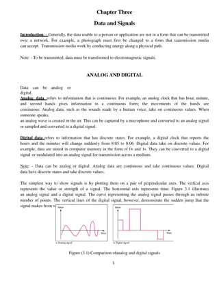
Explore the world of analog and digital electronics through the lens of registers, counters, and flip-flops. Dive deep into the operation of these components, learn how to transfer data between registers, build and analyze shift registers, construct timing diagrams, and understand binary counters. Discover the fundamentals of sequential circuits, state graphs, and more with practical applications and insights.

Download Presentation

Please find below an Image/Link to download the presentation.
The content on the website is provided AS IS for your information and personal use only. It may not be sold, licensed, or shared on other websites without obtaining consent from the author.If you encounter any issues during the download, it is possible that the publisher has removed the file from their server.
You are allowed to download the files provided on this website for personal or commercial use, subject to the condition that they are used lawfully. All files are the property of their respective owners.
The content on the website is provided AS IS for your information and personal use only. It may not be sold, licensed, or shared on other websites without obtaining consent from the author.
E N D
Presentation Transcript
1 ANALOG AND DIGITAL ELECTRONICS 21CS33
2 MODULE-5 Registers and Counters
3 Books Referred/Source Charles H Roth and Larry L Kinney, Analog and Digital Electronics, Cengage Learning,2019 Charles H Roth and Larry L Kinney, Fundamental of Logic Design, Cengage Learning, 2017. Donald P Leach, Albert Paul Malvino & Goutam Saha: Digital Principles and Applications, 7thEdition, Tata McGraw Hill, 2015 Anil K. Maini: Digital Electronics Applications, 2007, John Wiley & Sons, Ltd. Thomas L. Floyd: Digital Fundamentals, 9th Edition., Pearson International Edition. M. Morris Mano, Michael D. Ciletti : Digital Design With an Introduction to the Verilog HDL, 5thEdition, Pearson Education, Inc. Ronald J. Tocci, Neal S. Widmer, Gregory L. Moss: Digital systems : principles and applications 10th International Principles, Devices and Edition, Pearson Education
4 Objectives Explain the operation of registers. Show how to transfer data between registers using a tri-state bus. Explain the operation of shift registers, show how to build them using flip-flops, and analyze their operation. Construct a timing diagram for a shift register. Explain the operation of binary counters, show how to build them using flip-flops and gates, and analyze their operation. Given the present state and desired next state of a flip-flop, determine the required flip-flop inputs. Given the desired counting sequence for a counter. Construct a timing diagram for a counter by tracing signals through the circuit. Given a sequential circuit, write the next-state equations for the flip-flops and derive the state graph or state table. Using the state graph, determine the state sequence and output sequence for a given input sequence. Explain the difference between a Mealy machine and a Moore machine. Given a state table, construct the corresponding state graph, and conversely. Analyze a sequential circuit by signal tracing.
5 Introduction Each flip-flop can store one bit of information A register consists of a group of flip-flops with a common clock input. Registers are commonly used to store and shift binary data. Counters are another simple type of sequential circuit. A counter is usually constructed from two or more flip-flops which change states in a prescribed sequence when input pulses are received.
6 Registers and Register Transfers 4-Bit D Flip-Flop Registers with Data, Load, Clear, and Clock Inputs When Load = 0, the register is not clocked, and it holds its present value When Load = 1, the clock signal (Clk) is transmitted to the flip-flop clock inputs and the data applied to the D inputs will be loaded into the flip-flops on the falling edge of the clock.
7 Registers and Register Transfers 4-Bit D Flip-Flop Registers with Data, Load, Clear, and Clock Inputs If the Q outputs are 0000 (Q3 = Q2 = Q1 = Q0 = 0) and the data inputs are 1101 (D3 = 1, D2 = 1, D1 = 0 and D0 = 1), after the falling edge of the clock Q will change from 0000 to 1101 as indicated.
8 Registers and Register Transfers If flip-flops with clock enable are available When Load = 0, the clock is disabled and the register holds its data. When Load is 1, the clock is enabled, and the data applied to the D inputs will be loaded into the flip-flops, following the falling edge of the clock
9 Registers and Register Transfers A symbol for the 4-bit register using bus notation for the D inputs and Q outputs.
10 Registers and Register Transfers Data Transfer Between Registers Figure shows how data can be transferred from the output of one of two registers into a third register using tri-state buffers.
11 Registers and Register Transfers Data Transfer Between Registers If En = 1 and Load = 1, the output of register A is enabled onto the tri-state bus and the data in register A will be stored in Q after the rising edge of the clock. If En = 0 and Load = 1, the output of register B will be enabled onto the tri-state bus and stored in Q after the rising edge of the clock.
12 Registers and Register Transfers Logic Diagram for 8-Bit Register with Tri-State Output Figure (a) shows an integrated circuit register that contains eight D flip-flops with tri-state buffers at the flip-flop outputs. These buffers are enabled when En = 0. A symbol for this 8-bit register is shown in Figure (b).
13 Registers and Register Transfers Data Transfer Using a Tri-State Bus Figure shows how data can be transferred from one of four 8-bit registers into one of two other registers. 8 bits of data are transferred in parallel from register A, B, C, or D to register G or H or both.
14 Registers and Register Transfers Data Transfer Using a Tri-State Bus The operation as follows: If EF = 00, Ais stored in G (or H). If EF = 01, B is stored in G (or H). If EF = 10, C is stored in G (or H). If EF = 11, D is stored in G (or H). If LdG = 1, these signals on the bus are loaded into register G after the rising clock edge or into register H if LdH = 1.
15 Parallel Adder with Accumulator In computer circuits, it is frequently desirable to store one number in a register of flip-flops (called an accumulator) and add a second number to it, leaving the result stored in the accumulator. To build a parallel adder with an accumulator is to add a register to the full adder (FA).
16 Parallel Adder with Accumulator n-Bit Parallel Adder with Accumulator X = xn . . . x2x1 is stored in the accumulator Y= yn . . . y2 y1 is applied to the full adder inputs, The sum of X and Y appears at the adder outputs Add signal (Ad) is used to load the adder outputs into the accumulator flip- flops on the rising clock edge
17 Parallel Adder with Accumulator Before addition can take place, the accumulator must be loaded with X. This can be accomplished in two ways: Clear the accumulator Add multiplexers at the accumulator inputs Clear the accumulator using the asynchronous clear inputs on the flip-flops, and then put the X data on the Y inputs to the adder and add to the accumulator in the normal way.
18 Parallel Adder with Accumulator Add multiplexers at the accumulator inputs: So that we could select either the Y input data or the adder output to load into the accumulator.
19 Shift Registers A shift register is a register in which binary data can be stored, and this data can be shifted to the left or right when a shift signal is applied. Bits shifted out one end of the register may be lost, or if the shift register is of cyclic type, bits shifted out one end are shifted back in the other end.
20 Shift Registers TYPES OF REGISTERS
21 Shift Registers Right-Shift Register When Shift =1, the clock is enabled and shifting occurs on the rising clock edge. Shift = 0, no shifting and No changed in flip flop. The serial input (SI) is loaded into the first flip-flop (Q3) by the rising edge of the clock. At the same time, the output of the first flip-flop is loaded into the second flip- flop, the output of the second flip-flop is loaded into the third flip-flop, and the output of the third flip-flop is loaded into the last flip-flop
22 Shift Registers Right-Shift Register Shift register initially contains 0101. The serial input (SI) sequence is 1, 1, 0, 1. The sequence of shift register states is 0101, 1010, 1101, 0110, 1011.
23 Shift Registers Example: Show how a number 0100 is entered serially in a 4-bit shift register using D flip-flop. Also write state table.
24 Shift Registers Example: Suppose that it has the 4-bit number QRST = 1010 stored in it so draw the waveform Clk Serial In Q R S T 0 1 1 0 0 0 A 0 0 0 1 1 0 B 0 1 0 0 0 0 1 C 0 0 D 0 0 0 0
25 Shift Registers Cyclic Shift Register If we connect the serial output to the serial input, as shown by the dashed line, the resulting cyclic shift register performs an end-around shift. If the initial contents of the register is 0111, after one clock cycle the contents is 1011. After a second pulse, the state is 1101, then 1110, and the fourth pulse returns the register to the initial 0111 state.
26 Shift Registers 8-Bit Serial-In, Serial-Out Shift Register
27 Shift Registers 8-Bit Serial-In, Serial-Out Shift Register Serial in means that data is shifted into the first flip-flop one bit at a time, and the flip-flops cannot be loaded in parallel. Serial out means that data can only be read out of the last flip-flop
28 Shift Registers 4-bit parallel-in, parallel-out shift register
29 Shift Registers Shift register implemented using MUXes and D flip- flops (Universal shift register)
30 Shift Registers Shift register implemented using MUXes and D flip- flops
31 Shift Registers The next-state equations for the flip-flops are Q3+ = Sh L Q3 + Sh L D3 + Sh SI Q2+ = Sh L Q2 + Sh L D2 + Sh Q3 Q1+ = Sh L Q1 + Sh L D1 + Sh Q2 Q0+ = Sh L Q0 + Sh L D0 + Sh Q1 Sh L Q3+ Q2+ Q1+ Q0+ Action 0 0 Q3 Q2 Q1 Q0 No Change Parallel Data loaded from D3,D2,D1,D0 0 1 D3 D2 D1 D0 1 0 SI Q3 Q2 Q1 Serial input from SI 1 1 SI Q3 Q2 Q1
32 Shift Registers Timing Diagram for Shift Register Assuming that the register is initially clear (Q3Q2Q1Q0 = 0000), that the serial input is SI = 0 throughout, and that the data inputs D3D2D1D0 are 1011 during the load time (t0). Shifting occurs at the end of t1, t2, and t3, and the serial output can be read during these clock times
33 Shift Registers Timing Diagram for Shift Register The first clock pulse loads data into the shift register in parallel. During the next four clock pulses, this data is available at the serial output. Assuming that the register is initially clear (Q3Q2Q1Q0 = 0000), that the serial input is SI = 0 throughout, and that the data inputs D3D2D1D0 are 1011 during the load time (t0), the resulting waveforms are as shown. Shifting occurs at the end of t1, t2, and t3, and the serial output can be read during these clock times. During t4, Sh = L = 0, so no state change occurs.
34 Shift Registers A circuit that cycles through a fixed sequence of states is called a Counter. A shift register with non inverted feedback is called a Ring Counter or Cyclic Shift Register. A shift register with inverted feedback is called a Johnson Counter or a twisted ring counter.
35 Shift Registers Ring Counter. Clock Pulse Q0 Q1 Q2 Q3 0 1 0 0 0 1 0 1 0 0 2 0 0 1 0 3 0 0 0 1 4 1 0 0 0 5 0 1 0 0 6 0 0 1 0 7 0 0 0 1
36 Shift Registers Johnson Counter
37 Shift Registers Johnson counter Feedback) A 3-bit shift register with the Q1 output from the last fl ip-flop fed back into the D input of the first flip-flop. If the initial state of the register is 000, the initial value of D3 is 1, so after the first clock pulse, the register state is 100. (Shift Register with Inverted
38 Shift Registers General Shift Register Counter Figure shows the general form of a shift register counter where the bit being shifted into the leftmost stage can be a general function of the shift register contents. If the gate logic only contains exclusive-OR gates, the counter is called a linear (feedback) shift register counter. For each integer n, there exists a linear n-bit shift register counter that generates a count cycle of length 2n 1; all states are included except for the all 0 s state. Linear shift register counters have many applications, including as random number generators and as encoders and decoders for linear error-correcting codes.
39 Design of Binary Counters Flip-Flop Excitation Table: Excitation table of a flip-flop is looking at its truth table in a reverse way. Here, flip-flop input is presented as a dependent function of transition Qn Qn+ 1 and comes later in the table. This is derived from flip-flop truth table or characteristic equation and directly from its state transition diagram.
40 Design of Binary Counters Excitation table for SR Flip- Flop One can see if present state is 0 application of SR = 0x does not alter its value where 'x' denotes don't care condition in R input. State 0 to 1 transition occurs when SR = 10 is present at the input side While state 1 to 0 transition occurs if SR = 01. Present state l is maintained if SR = 0, i.e. SR = 00 or SR = 01.
41 Design of Binary Counters Example: A fictitious flip-flop with two inputs A and B functions like this. For AB= 00 and 11 the output becomes 0 and 1 respectively. For AB= 01, flip-flop retains previous output while output complements for AB= 10. Draw the truth table , excitation table and state transition diagrams of this flip-flop.
42 Design of Binary Counters DESIGN OF SYNCHRONOUS COUNTERS At any given time the memory is in a state called the present state and will advance to a next state on a clock pulse a determined by conditions on the excitation lines. Steps used in the design of the counter follows. In general, these steps can be applied to any sequential circuit: 1. Specify the counter sequence and draw a state diagram. 2. Derive a next-state table from the state diagram. 3. Develop a State (synthesis) Table or transition table showing the flip- flop inputs required for each transition. The transition table is always the same for a given type of flip-flop (Here will take JK flip-flop). 4. Transfer the J and K states from the transition table to Karnaugh maps. There is a Karnaugh map for each input of each flip-flop. 5. Group the Karnaugh map cells to generate and derive the logic expression for each flip-flop input. 6. Implement the expressions with combinational logic and combine with the flip- flops to create the counter. We follow the step with help of example as Mod-6 (Lab Experiment)
43 Design of Binary Counters Design a 3-bit or Mod-8 synchronous binary Up counter. (a) Use T flip-flops. (b) Use D flip-flops.
44 Design of Binary Counters State Diagram 000 111 001 110 010 101 011 100
45 Design of Binary Counters State (synthesis) Table or transition table
46 Design of Binary Counters Karnaugh Maps TA = 1 TC = BA TB = A.
47 Design of Binary Counters Counter Implementation (Circuit Diagram)
48 Design of Binary Counters Now using D- Flip Flip State (synthesis) Table or transition table Flip Flop Input DC DB DA 0 0 1 0 1 0 0 1 1 1 0 0 1 0 1 1 1 0 1 1 1 0 0 0
49 Design of Binary Counters Karnaugh Maps DC = C+ = C BA + CB + CA = C BA + C(BA) = C BA DB = B+ = BA + B A = B A DA = A+ = A
50 Design of Binary Counters Counter Implementation (Circuit Diagram)