Signal Encoding Techniques in Networks and Communication
This chapter delves into signal encoding techniques used in digital data transmission, covering key concepts such as encoding schemes like NRZ-L and NRZI, multilevel binary encoding, and biphase encoding. It explores the fundamentals of digital signaling, modulation techniques, and the relationship between analog and digital signals. The process of encoding digital data into digital signals is explained, highlighting the simplicity and cost-effectiveness of digital encoding equipment compared to analog modulation equipment.

Download Presentation

Please find below an Image/Link to download the presentation.
The content on the website is provided AS IS for your information and personal use only. It may not be sold, licensed, or shared on other websites without obtaining consent from the author.If you encounter any issues during the download, it is possible that the publisher has removed the file from their server.
You are allowed to download the files provided on this website for personal or commercial use, subject to the condition that they are used lawfully. All files are the property of their respective owners.
The content on the website is provided AS IS for your information and personal use only. It may not be sold, licensed, or shared on other websites without obtaining consent from the author.
E N D
Presentation Transcript
1 SIGNAL ENCODING TECHNIQUES Networks and Communication Department Chapter 5
Lecture Contents 2 Introduction Digital data, Digital signals Key terms Encoding schemes Nonreturn to Zero (NRZ-L , NRZI) Multilevel Binary (Bipolar-AMI , Pseudoternary) Biphase (Manchester , Differential Manchester) 27-Aug-24 Networks and Communication Department
Introduction 3 27-Aug-24 Networks and Communication Department
Introduction 4 27-Aug-24 Networks and Communication Department
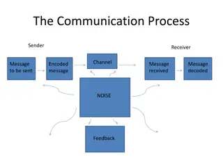
Introduction 5 For digital signaling, a data source g(t), which may be either digital or analog, is encoded into a digital signal x(t). The basis for analog signaling is a continuous constant-frequency fc signal known as the carrier signal. Data may be transmitted using a carrier signal by modulation, which is the process of encoding source data onto the carrier signal. All modulation techniques involve operation on one or more of the three fundamental frequency domain parameters: amplitude, frequency, and phase. The input signal m(t) may be analog or digital and is called the modulating signal, and the result of modulating the carrier signal is called the modulated signal s(t). 27-Aug-24 Networks and Communication Department
Introduction 6 Digital data, digital signals: simplest form of digital encoding of digital data the equipment is less complex and less expensive than digital-to-analog modulation equipment Digital data, analog signal: A modem converts digital data to an analog signal so that it can be transmitted over an analog medium Optical fiber and unguided media. Analog data, digital signals: Analog data, such as voice and video, are often digitized to be able to use digital transmission facilities. Use of modern digital transmission and switching equipment. Analog data, analog signals: Analog data are modulated by a carrier frequency to produce an analog signal in a different frequency band, which can be utilized on an analog transmission system Voice transmission and shift the bandwidth to other spectrum. 27-Aug-24 Networks and Communication Department
Digital data, Digital Signal 7 27-Aug-24 Networks and Communication Department
Digital Data, Digital Signal Digital signal A digital signal is a sequence of discrete, discontinuous voltage pulses Each bit is a signal element binary data encoded into signal elements the equipment for encoding digital data into a digital signal is less complex and less expensive than digital- to-analog modulation equipment
Key terms 9 Term Data element Unit Bits Definition A signal binary one or zero The rate at which data elements are transmitted The part of a signal that occupies the shortest interval of a signaling code Data rate Bits per second (bps) Digital: a voltage pulse of constant amplitude Signal element Analog: a pulse of constant frequency, phase, amplitude. Signal elements per second (baud) Signaling rate or Modulation rate The rate at which signal elements are transmitted 27-Aug-24 Networks and Communication Department
Some Terms Line coding schemes: Unipolar It uses only one voltage level . Polar use two voltage levels ,one positive and the other one negative . Bipolar - use three voltage levels ,positive voltage ,0 voltage and negative voltage
Interpreting Digital Signals Receiver needs to know timing of bits - when they start and end signal levels factors affecting signal interpretation Signal To Noise Ratio An increase in SNR decreases bit error rate. Data Rate An increase in data rate increases bit error rate (BER). Bandwidth An increase in bandwidth allows an increase in data rate Encoding Scheme affectsperformance
Comparison of Encoding Schemes Ways of evaluating or comparing the various encoding techniques: Signal Spectrum Lack of high frequencies reduces required bandwidth, lack of dc component provide isolation Number Of Signal Levels two levels (for binary) , or multilevel Clocking need for synchronizing transmitter and receiver either with an external clock or with a sync mechanism based on signal. Error Detection useful if can be built-in to signal encoding Signal Interference And Noise Immunity some codes are better than others Cost And Complexity Higher signal rate (& thus data rate) lead to higher costs.
Encoding Schemes Encoding scheme : is the mapping from data bits to signal element. They include: 1.Nonreturn to Zero-Level (NRZ-L( 2.Nonreturn to Zero Inverted (NRZI( 3.Bipolar -AMI 4.Pseudoternary 5.Manchester 6.Differential Manchester
Nonreturn to Zero-Level (NRZ-L) two different voltages for 0 and 1 bits negative voltage for one value and positive for the zero. voltage constant during bit interval no transition i.e. no return to zero voltage Lack of synchronization when the data contain a long streams of 0s or 1s.
Nonreturn to Zero Inverted (NRZI) Non-return to zero, inverted on ones constant voltage pulse for duration of bit data encoded as presence or absence of signal transition at beginning of bit time transition (low to high or high to low) denotes binary 1 no transition denotes binary 0 example of differential encoding since data is represented by changes rather than levels more reliable detection of transition rather than level easy to lose sense of polarity in twisted-pair line (for NRZ-L) Loss of synchronization when the data contain a long streams of 0s
NRZ Pros & Cons Pros easy to engineer make good use of bandwidth Cons dc component lack of synchronization capability used for magnetic recording not often used for signal transmission
Multilevel Binary Bipolar-AMI Use more than two levels Bipolar-AMI zero represented by no line signal one represented by positive or negative pulse One pulses alternately in polarity no loss of sync if a long string of ones long runs of zeros still a problem no net dc component lower bandwidth easy error detection
Multilevel Binary Pseudoternary one represented by absence of line signal zero represented by alternating positive and negative no advantage or disadvantage over bipolar-AMI each used in some applications
Multilevel Binary Issues synchronization with long runs of 0 s or 1 s can insert additional bits, c.f. ISDN scramble data . not as efficient as NRZ each signal element only represents one bit the receiver of multilevel binary signals has to distinguish between three levels : +A, -A, 0; instead of just two levels in the signaling formats previously discussed a 3 level system could represent log23 = 1.58 bits Because of this, the multilevel binary signal requires approximately 3 dB more signal power than a two-valued signal for the same probability of bit error.
Scrambling 21 Sequences that would result in a constant voltage level on the line are replaced by filling sequences that will provide sufficient transitions for the receiver s clock to maintain synchronization. The filling sequence must be recognized by the receiver and replaced with the original data sequence. The filling sequence is the same length as the original sequence, so there is no data rate penalty. 27-Aug-24 Networks and Communication Department
Scrambling use scrambling to replace sequences that would produce constant voltage these filling sequences must produce enough transitions to sync be recognized by receiver & replaced with original data be same length as original, no rate penalty The design goals for this approach can be summarized as follows: have no dc component have no long sequences of zero level line signal have no reduction in data rate give error detection capability
B8ZS and HDB3 Two techniques are commonly used in long-distance transmission services; these are illustrated below.
(1) B8ZS Substitution Rules: A coding scheme that is commonly used in North America is known as bipolar with 8-zeros substitution (B8ZS). If an octet of all zeros occurs and the last voltage pulse preceding this octet was positive, then the eight zeros of the octet are encoded as 000+ 0 +. If an octet of all zeros occurs and the last voltage pulse preceding this octet was negative, then the eight zeros of the octet are encoded as 000 +0+ .
high-density bipolar-3 zeros (HDB3) 25 A coding scheme that is commonly used in Europe and Japan is known as the high-density bipolar-3 zeros (HDB3). As before, it is based on the use of AMI encoding. In this case, the scheme replaces strings of four zeros with sequences containing one or two pulses. In each case, the fourth zero is replaced with a code violation. Table 5.4 shows that this condition is tested for by determining (1) whether the number of pulses since the last violation is even or odd and (2) the polarity of the last pulse 27-Aug-24 Networks and Communication Department
(2) HDB3 Substitution Rules: 26 The fourth zero is replaced with a code violation. Successive violations are of alternate polarity Number of Bipolar Pulses (ones) since Last Substitution Polarity of Preceding Pulse - + Odd 000- 000+ Even +00+ -00- 27-Aug-24 Networks and Communication Department
Bi-Phase Manchester Encoding overcomes the limitations of NRZ codes has transition in the middle of each bit period Mid-bit transition is used for both synchronization (clocking)and data representation low to high represents one high to low represents zero used by IEEE 802.3 (Ethernet LAN)
Bi-Phase Differential Manchester Encoding Mid-bit transition is clocking only transition at start of bit period representing 0 no transition at start of bit period representing 1 this is a differential encoding scheme used by IEEE 802.5 (Token Ring LAN)
Biphase Pros and Cons Cons at least one transition per bit time and possibly two maximum modulation rate is twice NRZ requires more bandwidth Pros synchronization on mid bit transition (self clocking) has no dc component has error detection: The absence of an expected transition can be used to detect errors
Modulation Rate o The modulation rate is the rate at which signal elements are generated. o One way of characterizing the modulation rate is to determine the average number of transitions that occur per bit time. In general, this will depend on the exact sequence of bits being transmitted.
Problems Q1. Assume a stream of ten 1 s. Encode the stream using the following schemes: NRZ-I, AMI, Manchester, Differential Manchester. Q2. For the Manchester encoded binary stream of the following, extract the clock information and the data sequence.
Problems Q3. Consider a stream of binary data consisting of a long sequence of 1s, followed by a zero, followed by a long sequence of 1s. Preceding bit and level is indicated within parentheses. Draw the waveforms for NRZI (high), AMI (1 as negative voltage), and pseudo- ternary (0 as negative voltage).
Problems Q4. The AMI waveform representing a sequence 0100101011 is transmitted over a noisy channel. The received waveform with a single error is shown in the following page. Locate the error with justification.
Digital data, Digital signal 34 Data and Computer Communications, Ninth Edition by William Stallings, Chapter 5 (5.1) Reference 27-Aug-24 Networks and Communication Department


 B8ZS Substitution Rules:")
")
 HDB3 Substitution Rules:")