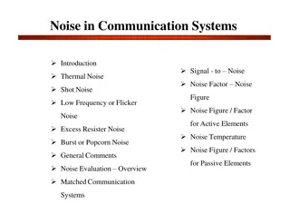
Overview of Communication Systems: Signal vs. Noise
Communication systems involve a battle between signal and noise/distortion, with information represented in analog or digital form. Analog signals include speech, music, and temperature readings, while digital signals can represent text and computer data. The history of analog and digital messages, from early analog communication like the telephone to modern digital methods such as the internet, showcases the evolution of communication technology over time.

Download Presentation

Please find below an Image/Link to download the presentation.
The content on the website is provided AS IS for your information and personal use only. It may not be sold, licensed, or shared on other websites without obtaining consent from the author.If you encounter any issues during the download, it is possible that the publisher has removed the file from their server.
You are allowed to download the files provided on this website for personal or commercial use, subject to the condition that they are used lawfully. All files are the property of their respective owners.
The content on the website is provided AS IS for your information and personal use only. It may not be sold, licensed, or shared on other websites without obtaining consent from the author.
E N D
Presentation Transcript
Chapter 1 Communication Systems Overview Communication is a battle between signal and noise/distortion
Chapter 1 Summary Information representation Communication system block diagrams Analog versus digital systems Performance metrics Data rate limits Next lecture: signals and signal space (L&D chapter 2) 9/26/2024 Chapter 1: Communication Systems Overview 2
Information Types Major classification of data: analog vs. digital Analog signals speech (words are sometimes discrete in time) music (closer to a continuous signal) temperature readings, barometric pressure, wind speed images stored on film Analog signals can be represented (approximately) using bits digitized images (can be compressed using JPEG) digitized video (can be compressed to MPEG) Bits: text, computer data Analog signals can be converted into bits by quantizing/digitizing The word bit (binary digit) was coined in the late 1940s by John Tukey. Today a byte is 8 bits. Originally it depended on the computer-6, 9, or 10 bits were also used. 9/26/2024 Chapter 1: Communication Systems Overview 3
Analog Messages Early analog communication Telephone (1876, Alexander Graham Bell) Phonograph (1877, Thomas Alva Edison) Film soundtrack (1923, Lee DeForest, Joseph Tykoci nski-Tykociner) Magnetic Recording (1899, Valdemar Poulsen & 1939, Marvin Camras) Key to early analog communication is the amplifier (1908, Lee DeForest, triode vacuum tube) Broadcast radio (AM, FM) is analog HD radio is digital Broadcast television (1927, Philo Farnsworth) was analog until 2009 now digital 9/26/2024 Chapter 1: Communication Systems Overview 4
Digital Messages Early long-distance communication was digital semaphores, white flag, smoke signals, drums, bugle calls, telegraph (1844, Samuel Morse) Teletypewriters (stock quotations) Emile Baudot (1874) created 5-unit code for alphabet. Today baud is a unit meaning one symbol per second. Working teleprinters were in service by 1924 at 65 words per minute Fax machines: Group 3 (voice lines) and Group 4 (ISDN) In 1990s the accounted for majority of transPacific telephone use. Sadly, fax machines are still in use. First fax machine was Alexander Bains 1843 device required conductive ink Pantelegraph (Giovanni Caselli, 1865) set up telefax between Paris and Lyon Ethernet, WiFi, Internet 9/26/2024 Chapter 1: Communication Systems Overview 5
Analog vs. Digital Systems Analog signals Values varies continuously Digital signals Value limited to a finite set Digital systems are more robust Binary signals Have 2 possible values Used to represent bit values Bit time T needed to send 1 bit Data rate R = 1/T bits per second 9/26/2024 Chapter 1: Communication Systems Overview 6
Sampling and Quantization, 1 2?? ? Quantization spacing is sampling interval is T (not shown in figure) 9/26/2024 Chapter 1: Communication Systems Overview 7
Sampling and Quantization, 2 Usually sample times are uniformly spaced. Higher frequency content requires faster sampling. (Soprano must be sampled twice as fast as a tenor.) Digital alues can be uniformly spaced, but nonuniform (logarithmic) spacing is often used for voice. 9/26/2024 Chapter 1: Communication Systems Overview 8
Digital Transmission and Regeneration Simplest digital communication is binary amplitude-shift keying (ASK) (a) binary signal input to channel; (b) signal altered by channel; (c) signal + noise; (d) signal after detection by receiver 9/26/2024 Chapter 1: Communication Systems Overview 9
Pulse Code Modulation (PCM) To communicate sampled values, we send a sequence of bits that represent the quantized value. For 16 quantization levels, 4 bits suffice. PCM can use binary representation of value. The PSTN uses companded PCM (similar to floating point) 9/26/2024 Chapter 1: Communication Systems Overview 10
Channel Errors If there is too much channel distortion or noise, receiver may make a mistake, and the regenerated signal will be incorrect. Channel coding is needed to detect and correct the message. 9/26/2024 Chapter 1: Communication Systems Overview 11
Digital Communication System Block Diagram (Basic) Source encoder converts message into message signal (bits) Transmitter converts message signal into format appropriate for channel transmission (analog/digital signal) Channel conveys signal but may introduce attenuation, distortion, noise, interference Receiver decodes received signal back to message signal Source decoder decodes message signal back into original message 9/26/2024 Chapter 1: Communication Systems Overview 12
Digital Communication System Block Diagram (Advanced) Source encoder compresses message to remove redundancy Encryption protects against eavesdroppers and false messages Channel encoder adds redundancy for error protection Modulator converts digital inputs to signals suitable for physical channel 9/26/2024 Chapter 1: Communication Systems Overview 13
Examples of Communication Channels Communication systems convert information into a format appropriate for the transmission medium Some channels convey electromagnetic waves (modulated signals). Radio (20 KHz to 20+ GHz) Optical fiber (200 THz or 1550 nm) Laser line-of-sight (e.g., from Mars) Other channels use sound, smell, pressure, chemical reactions (baseband signals) sound smell: ants chemical reactions: neuron dendrites dance: bees Analog communication systems convert (modulate) analog signals into modulated (analog) signals amplification to extend distance noise grows linearly Digital communication systems convert information in the form of bits into binary/digital signals bit regeneration to extend distance BER grows, but slowly 9/26/2024 Chapter 1: Communication Systems Overview 14
Physical Channels Physical channels have constraints on what kinds of signals can be transmitted Radio uses E&M waves at various frequencies Submarine communication at about 20 KHz Cordless telephones: 45 MHz, 900 MHz, 2.4 GHz, 5.8 GHz, 1.9 GHz Wired links may require DC balanced codes to prevent voltage build up Fiber optic channels use 4B5B (data redundancy) modulation to accommodate time-varying attenuation CD and DVD media require minimum spot size but position can be more precise The process of creating a signal suitable for transmission is called modulation (modulate from Latin to regulate) 9/26/2024 Chapter 1: Communication Systems Overview 15
Performance Metrics Analog communication systems Metric is fidelity, closeness to original signal We want A common measure of infidelity is the Mean Square Error (MSE): Digital communication systems Metrics are data rate R in bits/sec and probability of bit error Without noise, never make bit errors With noise, Pe depends on signal power, noise power, data rate, and channel characteristics. 9/26/2024 Chapter 1: Communication Systems Overview 16
Data Rate Limits Maximum data rate R is limited by signal power, noise power, distortion Without distortion or noise, we could transmit at R = and error probably Pe = 0 The channel capacity (1948, Claude Shannon) is the maximum possible data rate for a system with noise and distortion This maximum rate can be approached with bit probability close to 0 For additive white Gaussian noise (AWGN) channels (no distortion), notes: B = bandwidth,SNR = voltage ratio This theoretical result does not tell how to design real systems and assumes that you have forever to decide what bit was received. Engineers have spent the last 70 years trying to achieve speed approaching the channel capacity. Shannon obtained C = 32 Kbps for telephone channels (B=3kHz, SNR~30dB) Get higher rates with video modems/DSL (They use much more bandwidth) Chapter 1: Communication Systems Overview 9/26/2024 17


")

")
")