Interfacing with Analog Signals in Embedded Systems


Wireless Embedded Systems
Aaron Schulman
CSE190 Winter 2020
Lecture 11
Interfacing with
The Analog World

2
We live in an analog world
•
Everything in the physical world is an analog signal
–
Sound, light, temperature, pressure
•
Need to convert into electrical signals
–
Transducers: converts one type of energy to another
•
Electro-mechanical, Photonic, Electrical, …
–
Examples
•
Microphone/speaker
•
Thermocouples
•
Accelerometers
3
Going from analog to digital
•
What we want…
•
How we get there?
Physical
Phenomena
Engineering
Units
4
Representing an analog signal digitally
•
How do we represent an analog signal (e.g.
continuous voltage
)?
–
As a time series of discrete values
On MCU: read ADC data register (counts) periodically (
T
s
)
Voltage
(continuous)
Counts
(discrete
)
5
Choosing the sample rate
•
What sample rate do we need?
–
Too little: we can’t reconstruct the signal we care about
–
Too much: waste computation, energy, resources
6
Shannon-Nyquist sampling theorem
•
If a continuous-time signal contains no frequencies higher than ,
it can be completely determined by discrete samples taken at a rate:
•
Example:
–
Humans can process audio signals 20 Hz – 20 KHz
–
Audio CDs: sampled at 44.1 KHz
7
Use anti-aliasing filters on ADC inputs to
ensure that Shannon-Nyquist is satisfied
•
Aliasing
–
Different frequencies are indistinguishable when they are
sampled.
•
Condition the input signal using a low-pass filter
–
Removes high-frequency components
–
(a.k.a. anti-aliasing filter)
Do I really need to filter my input
signal?
•
Short answer: Yes.
•
Longer answer: Yes, but sometimes it’s already
done for you.
–
Many (most?) ADCs have a pretty good analog
filter built in.
–
Those filters typically have a cut-off frequency just
above ½ their
maximum
sampling rate.
•
Which is great if you are using the maximum sampling
rate, less useful if you are sampling at a slower rate.
8
9
Choosing the range
•
Fixed # of bits (e.g. 8-bit ADC)
•
Span a particular input voltage range
•
What do the sample values represent?
–
Some fraction within the range of values
What range to use?
10
Choosing the granularity
•
Resolution
–
Number of discrete values that
represent a range of analog values
–
12-bit ADC
•
4096 values
•
Range / 4096 = Step
Larger range
less info / bit
•
Quantization Error
–
How far off discrete value is from actual
–
½ LSB
Range / 8192
Larger range
larger error
11
Converting between voltages,
ADC counts, and engineering units
•
Converting: ADC counts
Voltage
•
Converting: Voltage
Engineering Units
12
A note about sampling and arithmetic*
•
Converting values in fixed-point MCUs
float vtemp = adccount/4095 * 1.5;
float tempc = (vtemp-0.986)/0.00355;
vtemp = 0! Not what you intended, even when vtemp is a float!
tempc = -277 C
•
Fixed point operations
–
Need to worry about underflow and overflow
•
Floating point operations
–
They can be costly on the embedded system
$ cat arithmetic.c
#include <stdio.h>
int main() {int adccount = 2048;
float vtemp;
float tempc;
vtemp = adccount/4095 * 1.5;
tempc = (vtemp-0.986)/0.00355;
printf("vtemp: %f\n", vtemp); printf("tempc: %f\n", tempc);}
$ gcc arithmetic.c
$ ./a.out
vtemp: 0.000000
tempc: -277.746490
13
Try it out for yourself…
Oversampling
•
One interesting trick is that you can use
oversampling to help reduce the impact of
quantization error.
–
Let’s look at an example of oversampling plus
dithering to get a 1-bit converter to do a much
better job…
14
Oversampling a 1-bit ADC w/ noise &
dithering (cont)
15
1
0
Count
Voltage
500 mV
0 mV
375 mV
N
1
= 11
N
0
= 32
uniformly
distributed
random noise
±250 mV
“upper edge”
of the box
V
thresh
= 500 mV
V
rand
=
500 mV
Note:
N
1
is the # of ADC counts that = 1 over the sampling window
N
0
is the # of ADC counts that = 0 over the sampling window
Oversampling a 1-bit ADC w/ noise &
dithering (cont)
•
How to get more than 1-bit out of a 1-bit ADC?
•
Add some noise to the input
•
Do some math with the output
•
Example
–
1-bit ADC with 500 mV threshold
–
Vin = 375 mV
ADC count = 0
–
Add
±
250 mV uniformly distributed random noise to
Vin
–
Now, roughly
•
25% of samples (N
1
) ≥ 500 mV
ADC count = 1
•
75% of samples (N
0
) < 500 mV
ADC count = 0
16
17
Can use dithering to deal with quantization
•
Dithering
–
Quantization errors can result in
large-scale patterns that don
’
t
accurately describe the analog
signal
–
Oversample and dither
–
Introduce random (white) noise
to randomize the quantization
error.
18
Selection of a DAC (digital to analog converter)
•
Error/Accuracy/Resolution:
Quantizing error
represents the difference between an actual
analog value and its digital representation.
Ideally, the quantizing error should not be
greater than ± 1⁄2 LSB.
Output Voltage Range
-> Input Voltage Range
•
Output Settling Time
-> Conversion Time
•
Output Coding
(usually binary)

Exploring the conversion of analog signals from the physical world into electrical signals using transducers in embedded systems. Learn about going from analog to digital representation, choosing sample rates, the Shannon-Nyquist sampling theorem, importance of anti-aliasing filters, and the necessity of filtering input signals for accurate data acquisition in embedded systems.

Download Presentation

Please find below an Image/Link to download the presentation.
The content on the website is provided AS IS for your information and personal use only. It may not be sold, licensed, or shared on other websites without obtaining consent from the author.If you encounter any issues during the download, it is possible that the publisher has removed the file from their server.
You are allowed to download the files provided on this website for personal or commercial use, subject to the condition that they are used lawfully. All files are the property of their respective owners.
The content on the website is provided AS IS for your information and personal use only. It may not be sold, licensed, or shared on other websites without obtaining consent from the author.
E N D
Presentation Transcript
CSE190 Winter 2020 Lecture 11 Interfacing with The Analog World Wireless Embedded Systems Aaron Schulman
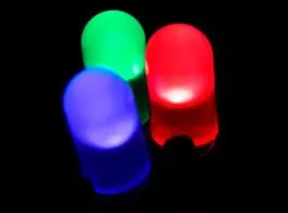
We live in an analog world Everything in the physical world is an analog signal Sound, light, temperature, pressure Need to convert into electrical signals Transducers: converts one type of energy to another Electro-mechanical, Photonic, Electrical, Examples Microphone/speaker Thermocouples Accelerometers 2
Going from analog to digital What we want Physical Phenomena Engineering Units How we get there? Engineering Units Physical Phenomena Voltage or Current ADC Counts Sensor ADC Software 3
Representing an analog signal digitally How do we represent an analog signal (e.g. continuous voltage)? As a time series of discrete values On MCU: read ADC data register (counts) periodically (Ts) (x ) f Counts (discrete) Voltage (continuous) (x ) fsampled t 4 S T
Choosing the sample rate What sample rate do we need? Too little: we can t reconstruct the signal we care about Too much: waste computation, energy, resources (x ) f (x ) fsampled 5 t
Shannon-Nyquist sampling theorem f (x ) f If a continuous-time signal contains no frequencies higher than , it can be completely determined by discrete samples taken at a rate: max 2f f samples max Example: Humans can process audio signals 20 Hz 20 KHz Audio CDs: sampled at 44.1 KHz 6
Use anti-aliasing filters on ADC inputs to ensure that Shannon-Nyquist is satisfied Aliasing Different frequencies are indistinguishable when they are sampled. Condition the input signal using a low-pass filter Removes high-frequency components (a.k.a. anti-aliasing filter) 7
Do I really need to filter my input signal? Short answer: Yes. Longer answer: Yes, but sometimes it s already done for you. Many (most?) ADCs have a pretty good analog filter built in. Those filters typically have a cut-off frequency just above their maximum sampling rate. Which is great if you are using the maximum sampling rate, less useful if you are sampling at a slower rate. 8
Choosing the range Fixed # of bits (e.g. 8-bit ADC) Span a particular input voltage range What do the sample values represent? Some fraction within the range of values What range to use? r V r V + + r V r V t t Range Too Big Range Too Small r V + r V t Ideal Range 9
Choosing the granularity Resolution Number of discrete values that represent a range of analog values 12-bit ADC 4096 values Range / 4096 = Step Larger range less info / bit Quantization Error How far off discrete value is from actual LSB Range / 8192 Larger range larger error 10
Converting between voltages, ADC counts, and engineering units Converting: ADC counts Voltage NADC= 4095 Vin-Vr- r V + Vr+-Vr- V in N Vin= NADC Vr+-Vr- ADC r V 4095 t Converting: Voltage Engineering Units = + 00355 . 0 V ( TEMP ) . 0 986 TEMP V C . 0 986 = TEMP TEMP C 00355 . 0 11
A note about sampling and arithmetic* Converting values in fixed-point MCUs VTEMP= NADC Vr+-Vr- . 0 986 =V TEMP TEMP C 00355 . 0 4095 float vtemp = adccount/4095 * 1.5; float tempc = (vtemp-0.986)/0.00355; vtemp = 0! Not what you intended, even when vtemp is a float! tempc = -277 C Fixed point operations Need to worry about underflow and overflow Floating point operations They can be costly on the embedded system 12
Try it out for yourself $ cat arithmetic.c #include <stdio.h> int main() { int adccount = 2048; float vtemp; float tempc; vtemp = adccount/4095 * 1.5; tempc = (vtemp-0.986)/0.00355; printf("vtemp: %f\n", vtemp); printf("tempc: %f\n", tempc); } $ gcc arithmetic.c $ ./a.out vtemp: 0.000000 tempc: -277.746490 13
Oversampling One interesting trick is that you can use oversampling to help reduce the impact of quantization error. Let s look at an example of oversampling plus dithering to get a 1-bit converter to do a much better job 14
Oversampling a 1-bit ADC w/ noise & dithering (cont) Voltage uniformly distributed random noise 250 mV Count upper edge of the box 1 Vthresh = 500 mV N1 = 11 500 mV 375 mV N0 = 32 500 mV Vrand = 0 0 mV t Note: N1 is the # of ADC counts that = 1 over the sampling window N0 is the # of ADC counts that = 0 over the sampling window 15
Oversampling a 1-bit ADC w/ noise & dithering (cont) How to get more than 1-bit out of a 1-bit ADC? Add some noise to the input Do some math with the output Example 1-bit ADC with 500 mV threshold Vin = 375 mV ADC count = 0 Add 250 mV uniformly distributed random noise to Vin Now, roughly 25% of samples (N1) 500 mV ADC count = 1 75% of samples (N0) < 500 mV ADC count = 0 16
Can use dithering to deal with quantization Dithering Quantization errors can result in large-scale patterns that don t accurately describe the analog signal Oversample and dither Introduce random (white) noise to randomize the quantization error. 17 Direct Samples Dithered Samples
Selection of a DAC (digital to analog converter) Error/Accuracy/Resolution: Quantizing error represents the difference between an actual analog value and its digital representation. Ideally, the quantizing error should not be greater than 1 2 LSB. Output Voltage Range -> Input Voltage Range Output Settling Time -> Conversion Time Output Coding (usually binary) 18


")