Digital to Analog Converters (DAC) and Their Applications
Digital to Analog Converters (DAC) are essential components used to convert digital signals into analog voltage or current outputs. This article explains the working principle of DACs, provides examples of different types such as Weighted Resistor DAC, R-2R Ladder DAC, Feedback Amplifier DAC, and Simple D/A Converter, and discusses how to calculate output voltages and resolutions. Explore the world of DACs to understand their significance in signal processing and electronic circuits.

Download Presentation

Please find below an Image/Link to download the presentation.
The content on the website is provided AS IS for your information and personal use only. It may not be sold, licensed, or shared on other websites without obtaining consent from the author.If you encounter any issues during the download, it is possible that the publisher has removed the file from their server.
You are allowed to download the files provided on this website for personal or commercial use, subject to the condition that they are used lawfully. All files are the property of their respective owners.
The content on the website is provided AS IS for your information and personal use only. It may not be sold, licensed, or shared on other websites without obtaining consent from the author.
E N D
Presentation Transcript
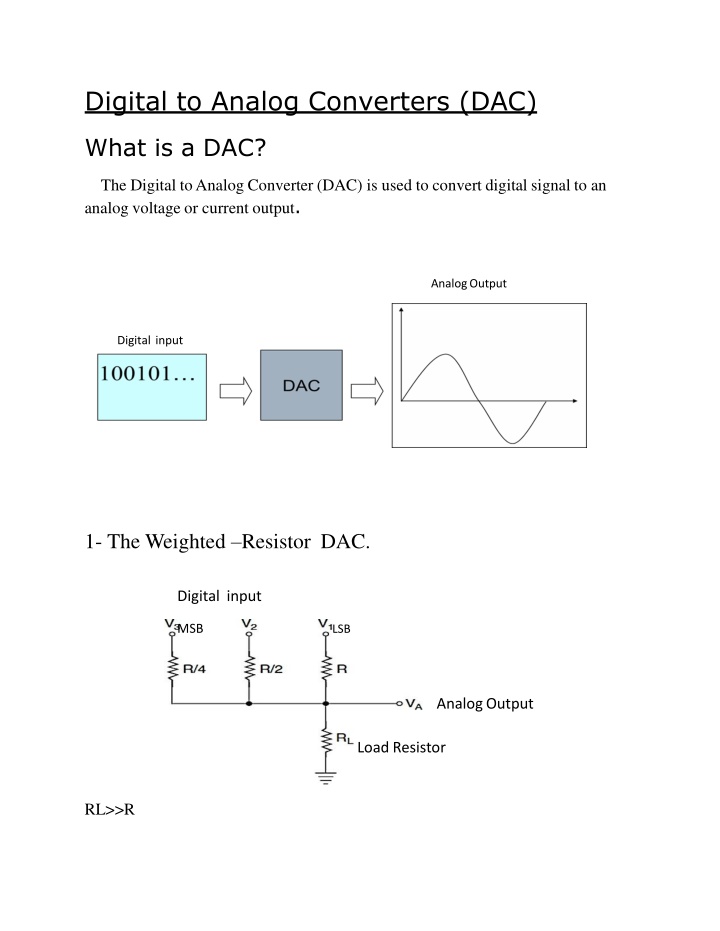
Digital to Analog Converters (DAC) What is a DAC? The Digital to Analog Converter (DAC) is used to convert digital signal to an analog voltage or current output. AnalogOutput Digital input 1- The Weighted Resistor DAC. Digital input MSB LSB AnalogOutput LoadResistor RL>>R
99 The output voltage, VA, may be found using Millman's theorem: Assume that: Logic "0" =0 V * VIH = VIN High Logic "1"=+7V Vo =ao2o + a121 + .+an 12n 1 2n 1 VinH Digital I/P Output Vo 0v 1v 2v 3v 4v 000 001 010 011 100
101 110 111 5v 6v 7v 100 Example 1: For a 4 input resistive divider (0=0V, 1=10V) find a. The full-scale output voltage. b. The output voltage change due to the LSB. c. The analog output voltage for a digital input of 1011. Sol.: a)The max. Output voltage occurs when all the input (1111) at +10V (ignoring the effects of RL). b)0 15 the LSB must be equal to 1/15 of the full scale output. Therefore the change in the output voltage due to the LSB is +10 * 1/15 = +2/3V c) Using Millman's theorem, the output voltage for a digital input of 1011 is: ao20+ a121+ + an 12n 1 2n 1 Vo = V H in 1 2o+ 1 21+0 22+1 23 24 1 Vo = 10 Vo =110 / 15 =7.33v
H.W: For a five-bit resistive divider, determine: a) The weight assigned to the LSB and also the second and the third LSB. B) The change in output voltage due to a change in the LSB. C)The output voltage for a digital input of 10110. Assume 0= 0V and 1= +10V. 101 2- The R-2R Ladder DAC. Digital Input Analog Output Assume that Logic "0" = 0 v Logic "1" = 10v o 1 n 1 Vo = ao2 +a12 + +an 12 VIH 2n
3- Feedback Amplifier DAC. Vo= F.B Resistor Ri Vref 102 For R1 = R, R2 = 2R, R3 = 4R, R4 = 8R, Ri = R [a1R+a2(2R)+a3(4R)+a4(8R)] V = Vref o R Vo = Vref(a1 + 2a2 + 4a3 + 8a4) Multiplying DAC [MDAC] i a = {0 Switch is closed 1 Switch is open} 4- Simple D/A converter using op-amp summing amplifier.
103 Example2: So we shall assume that 0 = 0V and 1 = 8V When input DCBA = 0000, then putting these value in above equation (1) we get: When digital input of the circuit DCBA = 0001, then putting these value in above equation (1) we get :
When digital input of the circuit DCBA = 0010, then putting these value in above equation (1) we get : Resolution: The number of bits making up the input data word that will ultimately determine the output step voltage as a percentage of full-scale output voltage. Example 3: Calculate the resolution of an 8-bit DAC. Solution: Resolution = 8 bits Percentage resolution = 104 Design of D/A Converter: To complete the design of the D/A converter, there must be a register which can be used to store the digital information, there must be level amplifiers between the register and the resistive network to insure that the digital signals presented to the network are all of the same level and are constant.
The level amplifiers each have two inputs: one input is the +10v from the precision voltage source, and the other is from a flip- flop. When the input from a flip- flop is high, the output of the amplifier is at +10v. When the input from the flip- flop is low, the output is 0v. 105 Example 4: Design a four bit digital to analog converter using the Ladder type as a resistive divider.
DigitalInput Four Bit Analog to DigitalConverter 106
")