PIP-II High Power RF Distribution System Overview
The PIP-II High Power RF Distribution System is a collaborative project involving various countries and institutions to develop a sophisticated system capable of efficiently distributing RF power to superconducting cavities. The system consists of multiple distribution lines and components designed to meet specific functional requirements, ensuring reliable operation and protection of equipment. Each cavity is powered by a Solid State Amplifier (SSA) through a distribution line that transports RF power. The system is engineered to handle power reflections, provide necessary signals for control and measurement, and ensure safe operation conditions. High-quality components and careful configuration are essential for the system's performance.

Download Presentation

Please find below an Image/Link to download the presentation.
The content on the website is provided AS IS for your information and personal use only. It may not be sold, licensed, or shared on other websites without obtaining consent from the author. Download presentation by click this link. If you encounter any issues during the download, it is possible that the publisher has removed the file from their server.
E N D
Presentation Transcript
PIP-II High Power RF Distribution System A Partnership of: US/DOE India/DAE Italy/INFN UK/UKRI-STFC France/CEA, CNRS/IN2P3 Poland/WUST Ding Sun AD/RF Department 8 September 2021
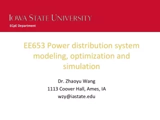
Overall RF functional requirement and engineering implements HB650/LB650 Distribution Line (650 MHz) SSR2 Distribution Line (325 MHz) SSR1 Distribution Line (325 MHz) HWR Distribution Line (162.5 MHz) 2 Ding Sun, PIP-II High Power RF Distribution System 10/4/2024
Definition of PIP-II RF distribution System SSA RF Distribution Line - - - - - - - Cavity Cryomodule HWR SSR1 x2 SSR2 x7 LB650 x9 HB650 x4 Figure 1. Definition of PIP-II RF Distribution System. Each cavity is powered by its own Solid State Amplifier (SSA). A distribution line connects the output port of the SSA to input port of the cavity and transports RF power from the SSA to the cavity . The overall configuration of all distribution lines are similar to each other, but using different type and size of the RF components and routing varies. Note: Per PIP-II definition, power amplifier and interlock system are not part of RF distribution system. 3 Ding Sun, PIP-II High Power RF Distribution System 10/4/2024
Functional requirement and Engineering implements for each distr. line RF functional requirement 1. Capable of transporting power sufficient to test superconducting cavities to 110% of their specified gradient along beam line. Capable of operating with fully reflected RF power at any phase when each cavity is operated in either pulsed or CW mode. Provide an isolator to keep reflected power under maximum level required by SSA (Solid State Amplifier). Provide forward and reflected power signals of each cavity to LLRF system and meet LLRF required technical specifications. These signals will be used for LLRF control, measurement of cavity gradient etc. Provide necessary signals to interlock system to protect SSA and distribution system from RF power should unsafe operation conditions exist before or during operation. 2. 3. 4. 5. Reference: PIP-II RF Distribution System Functional Requirement Specification Engineering implements to meet these functional requirements: 1 & 2 -> each component will have enough power handling capability and very low loss (max. 0.40 (0.45) db per line). 3 -> use a high quality / low loss isolator/circulator. 4 & 5 -> use two dual directional couplers; all distribution lines are pressurized. 4 Ding Sun, PIP-II High Power RF Distribution System 10/4/2024
Configuration of RF Distribution for HB650/LB650 Cavities 5 Ding Sun, PIP-II High Power RF Distribution System 10/4/2024
RF components list of one HB650/LB650 distribution line Custom-made (special specification) Quantity Standard Part Note 6 1/8 50 Ohm coaxial straight section TBD Yes 6 1/8 50 Ohm coaxial elbow TBD Yes 6 1/8 50 Ohm coaxial load (water cooled) 1 Yes 6 1/8 50 Ohm coaxial gas barrier 1 Yes WR1150 Dual Directional Coupler 2 Yes WR1150 Flexible Section TBD Yes WR1150 straight section (inch) TBD Yes WR1150 Bends TBD WR1150 Waveguide gas barrier 1 Yes WR1150 Waveguide Ferrite Junction Circulator 1 Yes WR1150 Waveguide-6-1/8" Coax Transition 2 Yes 6 Ding Sun, PIP-II High Power RF Distribution System 10/4/2024
Technical specification for RF components of HB650/LB650 distr. line To meet Functional Requirement, the following are technical specifications for components to be used: Overall specification (for all components): transport 58 kW (HB650) and 38.2 kW (LB650) forward power, operate in either pulsed or CW mode with full reflection at any phase, total attenuation: 0.4 db. Standard components power rating (average power): 6 1/8 coaxial line components: 70 kW @40 C, 80 kW (@27 C, (ambient temperature). WR 1150 waveguide components: 62 MW Calculated total attenuation of the longest line (113.2 feet: 100 feet Waveguide,13 feet Coax): 0.13 db Circulator loss: 0.15 db Measured insertion loss of a WR1150 transition: < 0.018 db/unit Other loss: 0.05 db Total attenuation: 0.37db 7 Ding Sun, PIP-II High Power RF Distribution System 10/4/2024
Technical specifications for Circulator Specification of 650 MHz 70 kW CW Waveguide Ferrite Junction Circulator Port configuration: 3 Ports, Port 1 (input port), Port 2 (output port), Port 3 (will be terminated with a water cooled termination by Fermilab) Orientation of Rotation: clockwise Flanges of all ports: WR1150 CPRF Center Frequency: 650 MHz Bandwidth (BW): 12 MHz Insertion loss: 0.13 db at center frequency, 0.3 db in BW VSWR at all ports: 1.10:1 at center frequency, 1.20:1 in BW Isolation: 26 db at center frequency, 20 db in BW Power handling capability: the circulator should function normally (meet all specification listed in this document, no sparking and no overheating should occur) under all operating conditions as follows: 1. Output power (CW) at Port 2: 0 - 70 kW, with full reflection back to Port 2 at ant phase while input power at Port 1 is at full level for 0 - 70 kW output power at Port 2 (the input power is ON). 2. At the end of each operation, immediately after the input power is shut off the stored energy in a superconducting cavity is released and generates return peak power of ~ up to 140 kW back to Port 2. This return power decays exponentially to 0 in ~ 3 millisecond. RF leakage: RF leakage at any joint should be less than 0.4 mW/cm2 measured at the closest distance from the joint. Pressurization: air tight up to 5 psig internal pressure. 8 Ding Sun, PIP-II High Power RF Distribution System 10/4/2024
Technical specifications for Circulator (cont.) Specification of 650 MHz 70 kW CW Waveguide Ferrite Junction Circulator Coolant: De-ionized water. Inlet cooling water temperature (optimum setting): 86 F 90 F Coolant connector: 1/2 NPT male connector, stainless steel The following green lines are for vendor to specify. Allowable inlet cooling water temperature range: Coolant flow rate (should be 10 GPM): Coolant pressure drop: Coolant input pressure: (should be 145 PSI) Coolant leak test pressure and duration of the test (in minutes): (for example: 15 bar for 10 minutes) Allowable ambient temperature range during operation: 15 C 40 C Temperature Compensating Unit: Data Sheet (function and technical specification) is required for bidding process. The circulator is required to satisfy all specifications listed in this document from startup to any steady state operating power levels (between 0 to 70 kW output power) at any power ramp rate without need for operator adjustment to the Temperature Compensating Unit (TCU). Magnetic Stray Field: < 5 Gausses at 1 meter distance Arc detectors and access ports must be installed. Mounting: tapped holes or brackets should be provided for mounting the circulator to a base metal plate. Lifting: eyelets for crane lifting. Test plan: High Power Test Plan of Fermilab PIP-II 650 MHz 70 kW Circulator 9 Ding Sun, PIP-II High Power RF Distribution System 10/4/2024
Technical specifications for Dual Directional Coupler SPECIFICATIONS of WR1150 Dual Directional Coupler Electrical: WR1150 Dual Directional Coupler (reflectometer) Power: 70 kW CW, with up to full reflection @ any phase Center Frequency: 650 MHz Bandwidth: 10 MHz (650 MHz +/- 5 MHz) Coupling: -50 +/-0.5 dB (forward & reverse, w/ factory calibrations labeled) Coupling Flatness: 0.1 db in the 650 MHz +/- 1 MHz frequency region and 0.3 db over bandwidth Directivity: > 40 dB directivity across bandwidth Mainline VSWR: < 1.02:1 over the bandwidth Mainline Insertion loss: < 0.01 dB over the bandwidth Coupling ports: dual broadwall (same side) loop couplers, external termination Coupling port: VSWR 1.10:1 over the bandwidth Coupling Port Connectors: Type N (non-teflon), 50 ohm impedance Coupling windows: Rexolite RF body leakage: < -60 dB Mechanical: Material: Aluminum 6061, corrosion resistant Flanges: standard WR1150, CPRF, 0.75" thick Wall thickness: 0.25" Length: 12 Pressurization: Air tight up to 5 psig internal pressure Other material: rad hard or radiation resistant materials capable to withstand up to 10 MRad accumulated dose Operating Life: 20 years minimum @ 6000 hr/year Finish: rohs compliant chemical conversion coating 10 Ding Sun, PIP-II High Power RF Distribution System 10/4/2024
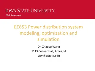
Configuration of RF Distribution for SSR2 Cavities 4 1/16" Coax Flexible 4 1/16" Coax Water Circulator * 4 1/16" Coax Termination INTERNAL PRESSURE: 3 PSIG Water 4 1/16" Coax Dual Directional Coupler 4 1/16" Coax (Straight, Elbow, Flexible...) 4 1/16" Coax Flexible 4 1/16" Coax Flexible 4 1/16" Coax Straight Section 4 1/16" Coax Dual Directional Coupler 4 1/16" Coax Gas Barrier 4 1/16" Coax Gas Barrier 4 1/16" to 3 1/8" Coaxial Reducer 4 1/16" to 3 1/8" Coaxial Reducer Input Power from SSA To Cavity Input Coupler 11 Ding Sun, PIP-II High Power RF Distribution System 10/4/2024
Configuration of RF Distribution for SSR2 Cavities 4 1/16" Coax Flexible 4 1/16" Coax Water * Circulator 3 1/8" Coax Termination INTERNAL PRESSURE: 3 PSIG Water 3 1/18" Coax Dual Directional Coupler 4 1/16" Coax (Straight, Elbow, Flexible...) 3 1/8" Coax Flexible 4 1/16" Coax Flexible 3 1/8" Coax Straight Section 4 1/16" Coax Dual Directional Coupler 3 1/8" Coax Gas Barrier 4 1/16" Coax Gas Barrier Input Power from SSA 4 1/16" to 3 1/8" Coaxial Reducer To Cavity Input Coupler 12 Ding Sun, PIP-II High Power RF Distribution System 10/4/2024
RF components list of one SSR2 distribution line Standard Part Custom-made (special specification) Quantity Note 4 1/16 50 Ohm coaxial straight section TBD Yes 4 1/16 50 Ohm coaxial elbow TBD Yes 4 1/16 (3 1/8 ) 50 Ohm coaxial load (water cooled) 1 Yes 4 1/16 50 Ohm coaxial gas barrier 1 Yes 4 1/16 Dual Directional Coupler 1 Yes 4 1/16 Flexible Section TBD Yes 3 1/8 50 Ohm coaxial straight section TBD Yes 3 1/8 50 Ohm coaxial elbow 1 3 1/8 50 Ohm coaxial gas barrier 1 Yes 3 1/8 Dual Directional Coupler 1 Yes 3 1/8 50 Ohm Flexible Section 1 Ferrite junction circulator 1 Yes 13 Ding Sun, PIP-II High Power RF Distribution System 10/4/2024
Technical specification for RF components of SSR2 distribution line To meet Functional Requirement, the following are technical specifications for components to be used: Overall specification (for all components): operating frequency 325 MHz, transport 17.2 kW forward power, operate in either pulsed or CW mode with full reflection at any phase, total attenuation: 0.4 db. Standard components power rating (average power): 4 1/8 coaxial line components (325 MHz) : ~45 kW @40 C, ~50 kW @27 C, (ambient temperature). 3 1/8 coaxial line components (325 MHz): ~28 kW @40 C ~31 kW @27C, (ambient temperature). Calculated total attenuation of the longest line (34.4 m/113 feet, 100 feet 4 1/16 Coax, 13 feet 3 1/8 Coax) : ~ 0.16 db Circulator loss: 0.15 db Other loss: 0.05 db Total attenuation: 0.36 db 14 Ding Sun, PIP-II High Power RF Distribution System 10/4/2024
Technical specifications for Circulator Specification of 325 MHz 20 kW CW Ferrite Junction Circulator Port configuration: 3 Ports, Port 1 (input port), Port 2 (output port), Port 3 (will be terminated with a water cooled termination by Fermilab) Orientation of Rotation: clockwise Flanges of all ports: 4 1/16 (3 1/8 ) EIA 50 Ohm Center Frequency: 325 MHz Bandwidth (BW): 6 MHz Insertion loss: 0.15 db at center frequency, 0.3 db in BW VSWR at all ports: 1.10:1 at center frequency, 1.20:1 in BW Isolation: 26 db at center frequency, 20 db in BW Power handling capability: the circulator should function normally (meet all specification listed in this document, no sparking and no overheating should occur) under all operating conditions as follows: 1. Output power (CW) at Port 2: 0 - 20 kW, with full reflection back to Port 2 at ant phase while input power at Port 1 is at full level for 0 - 20 kW output power at Port 2 (the input power is ON). 2. At the end of each operation, immediately after the input power is shut off the stored energy in a superconducting cavity is released and generates return peak power of ~ up to 40 kW back to Port 2. This return power decays exponentially to 0 in ~ 3 millisecond. RF leakage: RF leakage at any joint should be less than 0.4 mW/cm2 measured at the closest distance from the joint. Pressurization: Air tight up to 5 psig internal pressure 15 Ding Sun, PIP-II High Power RF Distribution System 10/4/2024
Technical specifications for Circulator (cont.) Specification of 325 MHz 20 kW CW Waveguide Ferrite Junction Circulator Coolant: De-ionized water. Inlet cooling water temperature (optimum setting): 86 F 90 F Coolant connector: 1/2 NPT male connector, stainless steel The following green lines are for vendor to specify. Allowable inlet cooling water temperature range: Coolant flow rate (should be 10 GPM): Coolant pressure drop: Coolant input pressure: (should be 145 PSI) Coolant leak test pressure and duration of the test (in minutes): (for example: 15 bar for 10 minutes) Allowable ambient temperature range during operation: 15 C 40 C Temperature Compensating Unit: Data Sheet (function and technical specification) is required for bidding process. The circulator is required to satisfy all specifications listed in this document from startup to any steady state operating power levels (between 0 to 20 kW output power) at any power ramp rate without need for operator adjustment to the Temperature Compensating Unit (TCU). Magnetic Stray Field: < 5 Gausses at 1 meter distance Arc detectors and access ports must be installed. Mounting: tapped holes or brackets should be provided for mounting the circulator to a base metal plate. Lifting: eyelets for crane lifting. 16 Ding Sun, PIP-II High Power RF Distribution System 10/4/2024
Technical specifications for Dual Directional Coupler SPECIFICATIONS of 325 MHz Coax Dual Directional Coupler Electrical: WR Dual Directional Coupler (reflectometer) Power: 20 kW CW, with up to full reflection @ any phase Center Frequency: 325 MHz Bandwidth: 5 MHz (325 MHz +/- 2.5 MHz) Coupling: -45 +/-0.5 dB (forward & reverse, w/ factory calibrations labeled) Coupling Flatness: 0.1 db in the 325 MHz +/- 1 MHz frequency region and 0.3 db over bandwidth Directivity: > 35 dB directivity across bandwidth Mainline VSWR: < 1.02:1 over the bandwidth Mainline Insertion loss: < 0.01 dB over the bandwidth Coupling ports: external termination Coupling port: VSWR 1.10:1 over the bandwidth Coupling Port Connectors: Type N (non-teflon), 50 ohm impedance Coupling windows: Rexolite RF body leakage: < -60 dB Mechanical: Material: Aluminum 6061, corrosion resistant Flanges: 4 1/16 (3 1/8 ) EIA 50 Ohm (rotatable) Length: 12 Pressurization: Air tight up to 5 psig internal pressure Other material: rad hard or radiation resistant materials capable to withstand up to 10 MRad accumulated dose Operating Life: 20 years minimum @ 6000 hr/year Finish: rohs compliant chemical conversion coating 17 Ding Sun, PIP-II High Power RF Distribution System 10/4/2024
Configuration of RF Distribution for SSR1 Cavities 3 1/8" Coax Flexible 3 1/8" Coax Water Circulator 3 1/8" Coax Termination INTERNAL PRESSURE: 3 PSIG Water * 3 1/8" Coax Dual Directional Coupler 3 1/8" Coax (Straight, Elbow, Flexible...) *3 1/8" Coax Flexible 3 1/8" Coax Flexible * 3 1/8" Coax Straight Section 3 1/8" Coax Dual Directional Coupler 3 1/8" Coax Gas Barrier 3 1/8" Coax Gas Barrier Input Power from SSA To Cavity Input Coupler 18 Ding Sun, PIP-II High Power RF Distribution System 10/4/2024
RF components list of one SSR1 distribution line Custom-made (special specification) Quantity Standard Part Note 3 1/8 50 Ohm coaxial straight section TBD Yes 3 1/8 50 Ohm coaxial elbow TBD Yes 3 1/8 50 Ohm coaxial load (water cooled) 1 Yes 3 1/8 50 Ohm coaxial gas barrier 2 Yes 3 1/8 Dual Directional Coupler 2 Yes 3 1/8 Flexible Section TBD Yes Ferrite junction circulator 1 Yes 19 Ding Sun, PIP-II High Power RF Distribution System 10/4/2024
Technical specification for RF components of SSR1 distribution line To meet Functional Requirement, the following are technical specifications for components to be used: Overall specification (for all components): operating frequency 325 MHz, transport 6.0 kW forward power, operate in either pulsed or CW mode with full reflection at any phase, total attenuation: 0.40 db. Standard components power rating (average power): 3 1/8 coaxial line components (325 MHz): 28 kW @40 C, 31 kW @27C, (ambient temperature). Calculated total attenuation of the longest line (37.2 m (122 feet) 3 1/8 Coax) : 0.2135 db Circulator loss: 0.15 db Other loss: 0.05 db Total attenuation: 0.4135 db 20 Ding Sun, PIP-II High Power RF Distribution System 10/4/2024
Configuration of RF Distribution for HWR Cavities 1 5/8" Coax Cable (Air Dielectrc) Water Circulator 1 5/8" Coax Termination INTERNAL PRESSURE: 3 PSIG Water 1 5/8" Coax Dual Directional Coupler 1 5/8" Coax Cable (Air Dielectric) * 1 5/8" Coax Flexible 1 5/8" Coax Cable (Air Dielectric) * 1 5/8" Coax Straight Section 1 5/8" Coax Dual Directional Coupler 1 5/8" Coax Gas Barrier 1 5/8" Coax Gas Barrier Input Power from SSA To Cavity Input Coupler 21 Ding Sun, PIP-II High Power RF Distribution System 10/4/2024
RF components list of one HWR distribution line Custom-made (special specification) Quantity Standard Part Note 1 5/8 50 Ohm coaxial straight section TBD Yes 1 5/8 50 Ohm coaxial elbow TBD Yes 1 5//8 50 Ohm coaxial load (water cooled) 1 Yes 1 5/8 50 Ohm coaxial gas barrier 2 Yes 1 5/8 Dual Directional Coupler 2 Yes 1 5/8 Flexible Section TBD Yes 1 5/8 50 Ohm Coax Cable (air dielectric) TBD Yes Ferrite junction circulator 1 Yes 22 Ding Sun, PIP-II High Power RF Distribution System 10/4/2024
Technical specification for RF components of HWR distribution line To meet Functional Requirement, the following are technical specifications for components to be used: Overall specification (for all components): operating frequency 162.5 MHz, transport 6.2 kW forward power, operate in either pulsed or CW mode with full reflection at any phase, total attenuation: 0.40 db. Standard components power rating (average power): 1 5/8 cable (162.5 MHz): 12.87 kW @40 C, (ambient temperature). 1 5/8 coaxial rigid line components (162.5 MHz): 11.6 kW @40 C 13 kW @27 C, (ambient temperature). Calculated total attenuation of the longest line (using 113 feet, same as SSR2 ) 1 5/8 Coax Cable: 0.2949 db Circulator loss: 0.15 db Other (joint contac, gas barrier): 0.05 db Total attenuation: 0.495 db 23 Ding Sun, PIP-II High Power RF Distribution System 10/4/2024
Technical specifications for Circulator Specification of 162.5 MHz 10 kW CW Ferrite Junction Circulator Port configuration: 3 Ports, Port 1 (input port), Port 2 (output port), Port 3 (will be terminated with a water cooled termination by Fermilab) Orientation of Rotation: clockwise Flanges of all ports: 1 5/8 EIA 50 Ohm (Rotatable) Center Frequency: 162.5 MHz Bandwidth (BW): 3 MHz (162.5MHz +/- 1.5 MHz) Insertion loss: 0.15 db at center frequency, 0.3 db in BW VSWR at all ports: 1.10:1 at center frequency, 1.20:1 in BW Isolation: 26 db at center frequency, 20 db in BW Power handling capability: the circulator should function normally (meet all specification listed in this document, no sparking and no overheating should occur) under all operating conditions as follows: 1. Output power (CW) at Port 2: 0 - 10 kW, with full reflection back to Port 2 at any phase while input power at Port 1 is at full level for 0 - 10 kW at Port 2 (the input power is ON). 2. At the end of each operation, immediately after the input power is shut off the stored energy in a superconducting cavity is released and generates return peak power of ~ up to 20 kW back to Port 2. This return power decays exponentially to 0 in ~ 3 millisecond. RF leakage: RF leakage at any joint should be less than 0.4 mW/cm2 measured at the closest distance from the joint. Pressurization: air tight up to 5 psig internal pressure. 24 Ding Sun, PIP-II High Power RF Distribution System 10/4/2024
Technical specifications for Circulator (cont.) Specification of 162.5 MHz 10 kW CW Ferrite Junction Circulator Coolant: De-ionized water. Inlet cooling water temperature (optimum setting): 86 F 90 F Coolant connector: 1/2 NPT male connector, stainless steel The following green lines are for vendor to specify. Allowable inlet cooling water temperature range: Coolant flow rate (should be 10 GPM): Coolant pressure drop: Coolant input pressure: (should be 145 PSI) Coolant leak test pressure and duration of the test (in minutes): (for example: 15 bar for 10 minutes) Allowable ambient temperature range during operation: 15 C 40 C Temperature Compensating Unit: Data Sheet (function and technical specification) is required for bidding process. The circulator is required to satisfy all specifications listed in this document from startup to any steady state operating power levels (between 0 to 10 kW output power) at any power ramp rate without need for operator adjustment to the Temperature Compensating Unit (TCU). Magnetic Stray Field: < 5 Gausses at 1 meter distance Arc detectors and access ports must be installed. Mounting: tapped holes or brackets should be provided for mounting the circulator to a base metal plate. Lifting: eyelets for crane lifting. 25 Ding Sun, PIP-II High Power RF Distribution System 10/4/2024
Technical specifications for Dual Directional Coupler SPECIFICATIONS of 162.5 MHz Coaxial Dual Directional Coupler Electrical: Coax Dual Directional Coupler (reflectometer) Power: 7 kW CW, with up to full reflection @ any phase Center Frequency: 162.5 MHz Bandwidth: 5 MHz (162.5 MHz +/- 2.5 MHz) Coupling: -40 +/-0.5 dB (forward & reverse, w/ factory calibrations labeled) Coupling Flatness: 0.1 db in the 162.5 MHz +/- 1 MHz frequency region and 0.3 db over bandwidth Directivity: > 35 dB directivity across bandwidth Mainline VSWR: < 1.02:1 over the bandwidth Mainline Insertion loss: < 0.01 dB over the bandwidth Coupling ports: external termination Coupling port: VSWR 1.10:1 over the bandwidth Coupling Port Connectors: Type N (non-teflon), 50 ohm impedance Coupling windows: Rexolite RF body leakage: < -60 dB Mechanical: Material: Aluminum 6061, corrosion resistant Flanges: 1 5/8 EIA 50 Ohm (Rotatable) Length: 12 Pressurization: Air tight up to 5 psig internal pressure Other material: rad hard or radiation resistant materials capable to withstand up to 10 MRad accumulated dose Operating Life: 20 years minimum @ 6000 hr/year Finish: rohs compliant chemical conversion coating 26 Ding Sun, PIP-II High Power RF Distribution System 10/4/2024
Past experience and future activity SSR1 and HWR and their distribution lines were successfully tested and used in PIPII-IT run in the past 2- 3 years (CMTF building) Performed high power test of 650 MHz single cavities up to 30 32 kw using an IOT currently and in the past (MDB building). But the long run of distribution line is 6 1/8 coax line plus a WR1150 6 1/8 coax transition. Plan to high power test 650 MHz 70 kW circulator using a 32 kW SSA late 2021 2022. Plan to perform high power test of HB 650 cavities (one by one, not simultaneously) using a 32 kW SSA in 2022 2023. But the long run of distribution line will be 6 1/8 coax line, WR1150 parts will be used only near the input port of the cavity. 27 Ding Sun, PIP-II High Power RF Distribution System 10/4/2024
Reference 1. PIP-II SRF High Power Radio Frequency Distribution Functional Requirements Specification ED0014228, Rev. 2. PIP-II 650MHz HPRF Distribution Technical Requirements Specification ED0014202 3. PIP-II 325MHz SSR2 HPRF Distribution Technical Requirements Specification ED0014257 4. PIP-II 325MHz SSR1 HPRF Distribution Technical Requirements Specification ED0014234 5. PIP-II 162.5MHz HWR HPRF Distribution Technical Requirements Specification ED0014236 6. PIP-II LB650, 650 MHz RF Amplifier Functional Requirement Specification ED0003413, Rev. B 7. PIP-II 650MHz TRS Meta-Data ED0014202 8. PIP-II 325MHz SSR2 HPRF RF Dist TRS Meta-Data ED0014257 9. PIP-II 325MHz SSR1 TRS Meta-Data ED0014234 10. PIP-II 162.5MHz HWR TRS Meta-Data ED0014236 28 Ding Sun, PIP-II High Power RF Distribution System 10/4/2024


")


")


")