Understanding Four-Bar Mechanisms in Mechanical Engineering

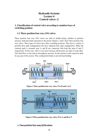
Four-bar mechanisms are essential components in mechanical engineering. They can be kinematically treated, making them suitable for various applications. The content covers the basics of four-bar linkages, the types of configurations, experimental procedures, and analysis involving angular displacement, velocity, and acceleration. Additionally, it explores practical applications such as piston rod displacement and force distribution on drive pins.

Uploaded on Oct 08, 2024 | 0 Views
Download Presentation

Please find below an Image/Link to download the presentation.
The content on the website is provided AS IS for your information and personal use only. It may not be sold, licensed, or shared on other websites without obtaining consent from the author. Download presentation by click this link. If you encounter any issues during the download, it is possible that the publisher has removed the file from their server.
E N D
Presentation Transcript
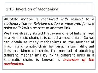
Four bar Mechanism Four bar Mechanism Mechanisms can be treated kinematic ally (without regard to the forces) if they are lightly loaded or are run at very low speeds. A four-bar linkage, also called a four-bar, is the simplest movable closed chain linkage. It consists of four bodies, called bars or links, connected in a loop by four joints. Generally, the joints are configured so the links move in parallel planes, and the assembly is called a planar four-bar linkage. If the linkage has four hinged joints with axes angled to intersect in a single point, then the links move on concentric spheres and the assembly is called a spherical four-bar linkage. Bennett's linkage is a spatial four-bar linkage with hinged joints that have their axes angled in a particular way that makes the system movable
Procedures Set the crank angle ( ) at zero degrees and record the angular displacement for another angle ( ). Move the crank angle by 30 and record the angular displacement. Repeat steps 1&2 for one complete revolution of the crank. Tabulate your results in the table given.
L2 =(Rsin - rsin)2+(G-Rcos - rcos)2 L=160mm r=40mm , R=100mm
Graph Plot a graph of the experimental angular displacement ( ) versus crank angle ( ) only. Discussion 1. Compare the experimental and theoretical velocity and acceleration. 2. How well do your experimental results agree with theory. 3. Where do maximum displacement, velocity and acceleration on the slide occur? Explain your answer. 4. Where dose maximum forces on the drive pin occur? Explain your answer. 5- Tabulate the application of all the mechanism above. piston rod displacement,


2+(G-Rcosα - rcosϴ)2")