Understanding Flash Descriptor in x86 Systems

Explore the internals of the Flash Descriptor in x86 systems, essential for BIOS and system management mode. Learn about SPI regions, determining SPI regions, flash protection mechanisms, and the structure of the Flash Descriptor for Intel systems. Complete with images and detailed explanations.

Download Presentation

Please find below an Image/Link to download the presentation.
The content on the website is provided AS IS for your information and personal use only. It may not be sold, licensed, or shared on other websites without obtaining consent from the author. Download presentation by click this link. If you encounter any issues during the download, it is possible that the publisher has removed the file from their server.
E N D
Presentation Transcript
Advanced x86: BIOS and System Management Mode Internals Flash Descriptor Xeno Kovah && Corey Kallenberg LegbaCore, LLC
All materials are licensed under a Creative Commons Share Alike license. http://creativecommons.org/licenses/by-sa/3.0/ Attribution condition: You must indicate that derivative work "Is derived from John Butterworth & Xeno Kovah s Advanced Intel x86: BIOS and SMM class posted at http://opensecuritytraining.info/IntroBIOS.html 2
SPI Regions Required Required Added in ICH9 Intel has left room for additional regions The only ones required are the Flash Descriptor region and the BIOS region They are not listed in the order in which they will appear on the flash chip: Flash Descriptor will always be first, as listed, but BIOS will always be last so it ends at 4 GB of memory address space 3
Determining SPI Regions You can determine the regions on your flash by reading the FREG(n) registers in the SPI Base Address Registers (SPIBAR + {54 to 64h}) FREG0 to FREG4, each 32 bits If the Base is higher than the limit, the region is unused 4
Flash Descriptor Defines most (but not all) of the flash protection that are supported by the Controller Hub Not defined in flash descriptor: BIOS Range Write Protection SMI# Global Write protection (described elsewhere) Logically OR d together, if either are set then access is blocked Must be written during the manufacturing process and set to Read-Only when it leaves the manufacturer, per Intel Sometimes (rarely) the Flash Descriptor itself is left open and thus vulnerable 5
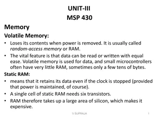
This "Flash Descriptor" structure is what's read by the ICH/PCH in order to populate and expose the information via RO registers (like FREG0) in SPIBAR Signature 0FF0A55Ah denotes the device has a valid descriptor and is therefore operating in Descriptor mode. Signature offset is located at 0 on ICH8, ICH9, and ICH10 In PCH it has been moved to 0x10 and bytes 0 thru 0x0F are Reserved Pictured: ICH 10 Flash Descriptor 6
Evolution of the Flash Descriptor from ICH to PCH ICH8 ICH9, ICH10 PCH Still 256 bits Still 256 bits Renamed Combined Offset shifted ICH 8, 9, 10 are identical 7
The registers of the Flash Descriptor used to be documented fully in the I/O Controller Hub datasheets. In the Platform Controller Hub datasheets, however, the Descriptor offsets and registers are no longer described. For this reason, we will use the image of the flash descriptor as taken from ICH10. FDBAR ICH10 used as example 8
When describing the protection mechanisms provided by the flash descriptor, I ll point out how they differ between ICH revisions where applicable Remember, this isn t an exercise in memorization but in acquiring new awareness and understanding, with that you can fill in details as they change in the future. The functionality described will be present, even if the offsets change in the future. Note: FDBAR is *not* a memory base address register. When you see later references to offsets from FDBAR, you re dealing in flash linear address offsets (so you need to be careful because FDBAR will differ depending on whether you re running an ICH (0) or PCH (0x10)) FDBAR ICH10 used as example 9
Signature Signature 0FF0A55Ah identifies a valid flash descriptor A valid flash descriptor indicates the SPI flash is operating in Descriptor mode PCH and Management Engine each require a valid flash descriptor Located at FDBAR + 0000h FDBAR defined in bits 12:0 in FREG0 (located in SPIBAR) Signature offset is located at 0 on ICH8, ICH9, and ICH10 In PCH it has been moved to 0x10 and bytes 0 thru 0x0F are Reserved FDBAR 10
Descriptor Map Describes the data structure of the Flash Descriptor number of sections in the descriptor pointers to these sections as well as the size of each section # of physical SPI flash chips present FLMAP1 FLMAP0 FDBAR 11
Region Identifies the different regions of the SPI Flash (BIOS, Mgt Eng, etc.) Not to be confused with defining the flash descriptor map. Each FLREG register (0-4) has a base and a limit, each corresponding to the range of that particular region FLREG0 = Flash Descriptor FLREG1 = BIOS FLREG2 = ME FLREG3 = GbE FLREG4 = Platform Data Disabled/unused regions will have a base of 1FFFh and a limit of 0000h Can determine what regions are active If BIOS region is inactive, then the BIOS is located on the FWH 12
Keeping it straight FLREG0-4 are what's in the Flash Descriptor. The data from the Descriptor is then exposed through FREG0-4 registers. 13
Master Defines the Read/Write capabilities that each Flash Master has with respect to each of the SPI regions, including the flash descriptor Each SPI Master has a register that defines these permissions called the Flash Master register Permissions apply only to register access 14
Flash Master Permissions Register layout is identical for each of the three masters Register location and layout is also identical across ICH8, ICH9, ICH10 Appears to be identical on PCH as well* Should never be set anywhere! *Based on John s analysis of SPI serial flash dumps 15
Flash Master Permissions The requestor ID of the master attempting to access a region must match that of the defined requestor ID 2-Byte value CPU and ME must have requestor ID s of 0h GbE must have a requestor ID of 0218h Each master will always have Read/Write permission to its own region CPU/BIOS will always be able to read the BIOS region of the SPI flash, and so on. This is by default and hardcoded by Intel BIOS 16
Example: FLMSTR meanings FLMAP1 (7:0) defines Master section location at 60h Master Section Based on analysis of the Descriptor Map (FLMAP offset 8h), we have identified that the Master section begins at offset 60h of the Serial Flash (06h is left-shifted 4 bits). FLMAP = 12100206h (bits 7:0 define Flash Master location) FLMSTR1 (CPU/BIOS) = 1A1B0000h FLMSTR2 (Mgt Engine) = 0C0D0000h FLMSTR3 (GbE) = 08080218h *HxD doesn t let you view the words in 32- bit format (with little-endian interpretation) 17
FLMSTR1 (CPU/BIOS) Master Section FLMSTR1 (CPU/BIOS) = 1A1B0000h Therefore CPU/BIOS has the following privileges: Write (bits 28:24) Can write to the Platform Data region of SPI Flash Can write to the BIOS region of SPI Flash Can write to the GbE region of SPI Flash Read (bits 20:16) Can read the Flash Descriptor of SPI flash Can read the BIOS region of SPI flash Can read the GbE region of SPI flash *Note: The FLMAP0 register defines 03h + 1 SPI regions, therefore there is no Platform Data region on this SPI flash. 18
CPU/BIOS Permissions = 1A1B0000h 1 1 1 0 A 1 0 1 1 1 0 B 1 1 0000 *Note: The FLMAP0 register defines 03h + 1 SPI regions, therefore there is no Platform Data region on this SPI flash. 19
ME Permissions = 0C0D0000h 0 0 1 1 C 0 0 0 0 1 1 D 0 1 0000 *Note: The FLMAP0 register defines 03h + 1 SPI regions, therefore there is no Platform Data region on this SPI flash. 20
GbE Permissions = 08080218h 0 0 1 8 0 0 0 0 0 1 8 0 0 0 0218 *Note: Requestor ID 0218h is required on ICH8, ICH9, and ICH10 systems, in PCH this is 0118h 21
Backup Deferred due to lack of time/importance for our purposes Included for completeness 22
Component Identifies the different flash chips themselves and their capabilities Read/Write/Erase clock frequencies Even if there are 2 SPI chips, there is still just a single component section The component section contains the Flash Invalid Instructions Register which says which instructions will be blocked from execution by the hardware 23
Yo Defines opcodes that will be prevented from running on the chip by the flash controller hardware Chip Erase (opcode 0xC7 is a good one to block) FLILL register is constant across ICH8, ICH9, ICH10 and appears to be the same on PCH* Same location (FCBA + 004h), same bit meanings *Based purely on my analysis of BIOS dumps on machines running PCH 24
Note on SPI Instructions (opcodes) Each ICH/PCH datasheet defines a minimal set of SPI commands that a chip must support H/W Sequencing Interoperability with Intel platform This table can serve a reference to identify any opcodes that are listed in the FLILL register However, each serial flash device may have unique capabilities and commands ICH 10 Required Opcodes *Write Enable looks interesting doesn t it? A future Advanced course goes into SPI Programming 25
Supported opcodes on an Atmel AT25DF321A SPI Serial Flash Taken straight from Atmel s datasheet Supports more than the minimum set required by Intel Notice it supports more than one Chip Erase command FLILL register must be filled out with these opcodes in mind, not just those that Intel lists http://www.atmel.com/Images/doc3633.pdf 26
FLILL = 00000000h Looking at the Flash Invalid Instructions Register from the Copernicus BIOS dump, we can see that none are defined Although only 4 opcodes can be black-listed here, it s still a setting that should be used And the SPI Flash vendor s datasheet should be taken into account when defining forbidden opcodes I don t recall any other source that has provided this recommendation 27
Soft Straps First implemented in ICH8 In PCH, both regions are combined into a single PCH Soft Straps section Soft Strap data is read out of the SPI device prior to de-asserting a reset (power-on, in layman s terms) Configure specific functions within the chipset before the BIOS or any other software can intervene The specific details regarding the implementation of Soft Straps are located in Intel s confidential SPI programming guides 28
OEM Section and Descriptor Upper MAP OEM Section *CH does not read the OEM information 256 bytes (ICH8, ICH9, ICH10, and PCH (up thru 8-series PCH1) Descriptor Upper MAP Describes the Base and length of the Management Vendor Specific Component Capabilities (VSCC) Table Base address is at FDBAR + EFCh (ICH8, ICH9, ICH10, and PCH2) Recall FDBAR is offset 10h on the flash chip on PCH, 0h on all others 1Most recent PCH at the time of this writing 2 Based on my analysis of BIOS binaries FDBAR 29
Management Engine VSCC* Table Contains the JEDEC ID of the Flash Chip Identifies the Vendor and Device ID of the SPI serial flash Describes the different attributes an SPI partition can have (Upper or Lower) Based on the value defined in the FPBA flash descriptor register in the Master section If SPI is defined as having one single partition, then only the attributes defined for the Upper partition are used. *VSCC = Vendor Specific Component Capabilities 30


")


")