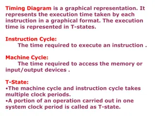
Understanding Processor Cycles and Machine Cycles in 8085 Microprocessor
Processor cycles in microprocessors like 8085 involve executing instructions through machine cycles that are essential operations performed by the processor. In the 8085 microprocessor, there are seven basic machine cycles, each serving a specific purpose such as fetching opcodes, reading from memory, writing to memory, performing I/O operations, handling interrupts, and idling on the bus. The timing of these machine cycles is crucial, measured in T states which represent the time taken to execute a machine cycle. Opcode fetch and memory read cycles are integral parts of instruction execution, involving specific operations during each T state. Understanding these cycles is fundamental to comprehending the functioning of the 8085 microprocessor.

Uploaded on Sep 27, 2024 | 0 Views
Download Presentation

Please find below an Image/Link to download the presentation.
The content on the website is provided AS IS for your information and personal use only. It may not be sold, licensed, or shared on other websites without obtaining consent from the author. Download presentation by click this link. If you encounter any issues during the download, it is possible that the publisher has removed the file from their server.
E N D
Presentation Transcript
8085-unit 1 Timing diagram for memory read & memory write cycles
Processor cycles The sequence of operations that a processor has to carry out while executing the instruction is called instruction cylce. Each instruction cycle of a processor in turn consists of a number of machine cycles. The machine cycles are the basic operations performed by the processor. To execute an instruction, the processor executes one or more machine cycles in a particular sequence. The machine cycles of a processor are also called processor cycles. The manufactures of microprocessors define the timings and status of various signals during the processor cycles.
In general, the instruction cycle of an instruction can be divided into two sub cycles. 1) Fetch cycle 2) Execute cycle The fetch cycle is executed to fetch the opcode from memory and the execute cycle is executed to decode the instruction and to perform the work specified by the instruction.
Machine cycles of 8085 The 8085 microprocessor has seven basic machine cycles. They are as follows. 1) Opcode fetch cycle (4T 0r 6T) 2) Memory read cycle (3T) 3) Memory write cycle(3T) 4) IO read cycle (3T) 5) IO write cycle(3T) 6) Interrupt acknowledge cycle (6T or 12T) 7) Bus idle cycle (2T or 3T)
The definite time to execute the machine cycles. The time taken by the processor to execute a machine cycle is expressed in T states. One T-state is equal to the time period of the internal clock signal processor. processor takes a of the
Opcode Fetch This cycle is used to fetch the opcode from the memory This is the first maschine cycle of every instruction It is a compulsory machine cycle It is generally of 4T states. During T1 A15-A8contains the higher byte of the address As ALE is high AD7-AD0contains the lower byte of the address Since it is an opcode fetch cycle S1 and S0 go high Since it a memory operation IO/M goes low During T2 As ALE goes low address is removed from AD7-AD0 AS RD goes low, data appears on AD7-AD0 During T3 Data remains on AD7-AD0 till RD is low During T4 T4 stat is used by the microprocessor to decode the opcode
Memory Read During T1 A15-A8contains the higher byte of the address As ALE is high AD7-AD0contains the lower byte of the address Since it is a memory read cycle S1 goes high and S0 go low Since it a memory operation IO/M goes low During T2 As ALE goes low address is removed from AD7- AD0 AS RD goes low, data appears on AD7-AD0 During T3 Data remains on AD7-AD0 till RD is low
Memory write During T1 A15-A8contains the higher byte of the address As ALE is high AD7-AD0contains the lower byte of the address Since it is a memory write cycle S0 goes high Since it a memory operation IO/M goes low During T2 As ALE goes low address is removed from AD7-AD0 AS RD goes low, data appears on AD7- AD0 During T3 Data remains on AD7-AD0 till WR is low
INTERRUPT The process of interrupting the normal program execution to carry out a specific task/work is referred to as interrupt. The interrupt is initiated by a signal generated by an external device or by a signal generated internally to the processor. When a microprocessor receives an interrupt signal is stops executing current normal program, save the status (or content) of various registers in stack and then the processor executes a subroutine /procedure in order to perform the specific task/work requested by the interrupt. The interrupts are useful for efficient data transfer between processor and peripheral.
Classification of Interrupts In general the interrupts can be classified in the following three ways. i. ii. iii. Hardware and software interrupts Vectored and non-vectored interrupts Maskableand non-maskable interrupts Hardware and software interrupts The interrupts initiated by external hardware by sending an appropriate signal to the interrupt pin of the microprocessor is called hardware interrupt. The 8085 has five interrupt pins TRAP, RST 7.5, RST 6.5, RST 5.5 and INTR. The software interrupts are program instructions. These instructions are inserted at derived locations in a program. The software interrupts of 8085 are RST 0, RST 1, RST 2, RST 3, RST 4, RST 5, RST 6 and RST 7.
Vectored and non-vectored When an interrupt signal is accepted by the microprocessor, if the program control automatically branches to a specific address (called vector address) then the interrupt is called vectored interrupts. In non-vectored interrupt there is no specific address for storing the interrupt service routine. Hence the interrupting device should give the address of the interruptservice routing.
Maskable and Non-maskable The processors have the facility for accepting or rejecting hardware interrupts. Programming the processor to reject an interrupt is referred to as masking or disabling and programming the processor to accept an interrupt is referred toas unmasking orenabling. In 8085 the interrupts RST 7.5, RST 6.5 and RST 5.5 can be masked/unmasked using SIM (set interrupt mask) instruction. All the hardware interrupts except TRAP are disabled by executing DI instructionand theyareenabled by EI instruction. The interrupts whose request can be either accepted or rejected by the processor are called maskable interrupts (RST 7.5, RST 6.5 ,RST 5.5 and INTR). The interrupts whose request has to be definitely accepted (or cannot be neglected) by the processor are called non-maskable interrupts (TRAP)
Priorities of the Interrupt When all the interrupts are enabled, the priority of hardware interrupts from highest to lowest is TRAP ( it is a non-maskable interrupt) RST 7.5 RST 6.5 RST 5.5 and INTR
Addressing modes Every instruction of a program has to operate on a data. The method specifying the data to be operated by the instructions called addressing. The 8085 supports the following fiveaddressing modes. Direct addressing Register addressing Register indirect addressing Immediate addressing Implied addressing/implicit addressing
i) Direct Addressing In direct addressing mode, the address of the data is specified in the instruction. The data will be in memory. In this addressing mode, the program instructions and data can be stored in different memory locations. Example: LDA 1050H -load the data available in memory location 1050H in accumulator ii) Register addressing In register addressing mode, the instruction specifies the name of the Register in which the data is available. Example: MOV A, B- move the content of B register to A iii) Register indirect addressing In this mode, the instruction specifies the name of the register in which the address of the data is available. Here the data will be in memory and the address will be in a register pair. Example: MOV A, M - the memory data addressed by HL pair is moved to A-register
iV) Immediate addressing The data is specified in the instruction itself. The data will be a part of the program instruction. Example: MVI B, 3EH move the data 3EH given in the instruction to B register v) Implied addressing The instruction itself specifies the data to operated. Example: CMA - complement the content of accumulator.


 Immediate addressing")